Richmond GTR099 Скачать руководство пользователя страница 3

GTR099 swing gate opener manual – Revision 22 

3


Safety Installation Information 

1.


READ and FOLLOW all instructions. 

2.


The gate opener is intended for use with Class I 
vehicular swing gates. Class I denotes a vehicular gate 
opener (or system) dwelling, or a garage or parking 
area associated therewith. Install the gate opener only 
when the opener is appropriate for the construction 
and the usage class of the gate. 

3.


Gate opening system designers, installers and users 
must consider the possible hazards associated with 
each individual application. Improperly designed, 
installed, or maintained systems can create risks for 
the user as well as the bystander. Gate system design 
and installation must reduce public exposure to 
potential hazards. All exposed pinch points must be 
eliminated or guarded. 

4.


A gate opener can create high levels of force during 
normal operation. Therefore, safety features must be 
incorporated into every installation. Specific safety 
features include safety sensors. 

5.


The gate must be properly installed and work freely in 
both directions prior to the installation of the gate 
opener. 

6.


The gate must be installed in a location so that enough 
clearance is provided between the gate and adjacent 
structure when opening and closing to reduce the risk 
of entrapment. Swinging gates shall not open into 
public access areas. 

7.


The opener is intended for use only on gates used for 
vehicles. Pedestrians must be supplied with a separate 
access opening. The pedestrian access opening shall 
be designed to promote pedestrian usage. The 
pedestrian access shall be located such that persons 
will not come in contact with the moving vehicular 
gate.  
 

8.


Pedestrians should never cross the pathway of a 
moving gate. The gate opener is not acceptable for 
use on any pedestrian gate. Pedestrians must be 
supplied with a separate pedestrian access. 

9.


 For an installation utilizing non-contact sensors 
(safety sensors), see product manual on the 

placement of non-contact sensors (safety sensors) for 
each type of application. 

a.

 Care shall be exercised to reduce the risk of 

nuisance tripping, such as when a vehicle trips the 
safety sensor while the gate is still moving. 

b.

 One or more non-contact sensors (safety sensors) 

shall be located where the risk of entrapment of 
obstruction exists, such as the perimeter reachable by 
a moving gate or barrier. 

10.


 Never mount any device that operates the gate 
opener where the user can reach over, under, around 
or through the gate to operate the controls. Controls 
are to be placed at least 6’ (1.8m) from any part of the 
moving gate. 


11.


Controls intended to be used to reset an operator 
after 2 sequential activations of the entrapment 
protection device or devices must be located in the 
line of sight of the gate, or easily accessible controls 
shall have a security feature to prevent unauthorized 
use. Never allow anyone to hang on or ride the gate 
during the entire travel of the gate. 
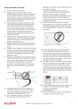
12.


Each gate opener is provided with two safety warning 
placards. The placards are to be installed on the front 
and back of the gate where they are plainly visible. 
The placards may be mounted using cable ties through 
the four holes provided on each placard. All warning 
signs and placards must be installed where visible near 
the gate. 
 

13.


To AVOID damaging gas, power, or other underground 
utility lines, contact underground utility locating 
companies BEFORE digging. 
SAVE INSTRUCTION 

14.


Do not permit children to play on or around the gate 
and keep all controls out of their reach.


Содержание GTR099

Страница 1: ...se read and follow all warnings precautions and instructions before installation and use 2 x 12V 7Ah batteries are supplied The AC adaptor included is used to maintain charge in the batteries Periodic...

Страница 2: ...echnical Specifications Features 6 Installation Overview 9 Preparation for Installation 9 Install the Gate Opener on the Gate 10 Mounting of the control box 16 Connection of the power supply 16 Connec...

Страница 3: ...ar gate 8 Pedestrians should never cross the pathway of a moving gate The gate opener is not acceptable for use on any pedestrian gate Pedestrians must be supplied with a separate pedestrian access 9...

Страница 4: ...GTR099 swing gate opener manual Revision 22 4 Parts List...

Страница 5: ...tional Accessories Tools Needed Power Drill Tape Measure Open End Wrenches 14mm 17mm or Adjustable Wrenches Wire Strippers C Clamps small medium and large Level Hacksaw or Heavy Duty Bolt Cutters Phil...

Страница 6: ...ns Retracted Gate Arm Dimensions Extended Gate Arm Dimensions Specifications GTR099 Fuse F5L250V or F5AL250V Input 120V 60Hz or 230V 50Hz Motor voltage 24VDC Power 80W Current 3A Actuator speed 16mm s...

Страница 7: ...GTR099 swing gate opener manual Revision 22 7 Dimensions Gate Bracket Dimensions Post Bracket Dimensions Post Pivot Bracket Dimensions...

Страница 8: ...failure Stop in case of obstruction during gate opening Reverse in case of obstruction during gate closing Built in adjustable auto close 0 100 seconds Built in max Motor running time MRT for additio...

Страница 9: ...e Post Brackets are curved When mounting the Post Brackets use bolts long enough to pass through the entire post M10 x 200 bolts are included Concrete anchors are not provided When mounting the Post B...

Страница 10: ...gate for a given A and B For example if A is 15cm and B is 20cm the maximum opening angle of the gate is 110 Pull to Open Installation Gate in Closed position Moving Rod is extended Note for best perf...

Страница 11: ...sert the M10 x 30 bolt through the centre hole of the post bracket and post pivot bracket as shown Place a 10 washer 10 lock washer and M10 nut on the bottom of the bolt and hand tighten 2 Attach the...

Страница 12: ...osition the Post Bracket Assembly and Gate Bracket so that the gate opener is level While holding the gate opener in the level position temporarily secure it with two C clamps 5 Make sure that there i...

Страница 13: ...cket assemblies and the gate bracket It allows slight adjustments to the post bracket Then remove the post bracket and gate bracket by taking off the C clamps Please Note Each swing arm contains an in...

Страница 14: ...holes in the gates 10 Cut off any part of the bolts that extend beyond the tightened nuts 11 With the gate opener fully retracted and with the gate in the fully open position for Pull to Open install...

Страница 15: ...from the hinge point will make the gate stop at a later point when closing To adjust the limit switch use a screwdriver to loosen the screw of Limit Switch A slide to the correct position and then tig...

Страница 16: ...e note the wire connection of them is very important Incorrect wire connection may damage the control board The battery used should be waterproof or you should place them in a waterproof case Please e...

Страница 17: ...charge controller refer to website for solar panel and battery connections You can plug the transformer into the electrical outlet after all the wire connections are completed Use a surge protector wi...

Страница 18: ...GTR099 swing gate opener manual Revision 22 18 Connection of the Control Board...

Страница 19: ...o MOTOR terminal 18 the blue wire into DLMT terminal 19 the green wire into COM terminal 20 and the yellow wire into ULMT terminal 21 2 Battery optional The 24V of the battery should be wired to the B...

Страница 20: ...use an optional external receiver How to use the Remote to Operate your Gate Opener Each remote has four buttons from top to bottom are separately A B C and D You may use this remote to operate as ma...

Страница 21: ...lose function enable disable photobeam function DIP Switch 1 Select push pull to open If the gate opens INTO the property pull to open the DIP Switch is set to OFF factory default setting If your gate...

Страница 22: ...o decrease the stall force Potentiometer B Used to adjust the auto close time of the gate opener Turn the potentiometer clockwise to increase the auto close time and turn it counter clockwise to decre...

Страница 23: ...the force 2 Disconnect the gate from the gate operator and check that the gate slides freely without any binding Gate opener does not run when you press the remote control 1 Make sure the connection...

Страница 24: ...12v charger to recharge your battery When recharging your battery always remember to connect the positive charger red output to the positive battery terminal The negative charger output black connects...

Отзывы: