background image

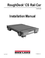
RoughDeck CS Rail Car Coil Scale

10

Visit our website 

www.RiceLake.com

6.0

Troubleshooting

If the system powers up and give some type of stable digital readout that varies with the load on the systems, any system 

problems are probably caused by factors other than load cells. The load cells are often blamed for a malfunctioning system, but 

the majority of the time, the problems exists elsewhere. Look for mechanical causes for your problem first.
If the system can be calibrated but doesn’t return to zero, loses calibration or demonstrates non-linearity or non-repeatability, 

see 

Table 6-1

 for possible causes and do the following checks.

1. Check the load cell mount for debris restricting load cell movement or debris between the scale and structure.
2. Check that tank/vessel and mounts are plumb, level and square at the critical areas.
3. Check all piping and conduit for connections that restrict movement.
4. If check rods are used, loosen all connections to finger tightening only for testing.
5. Check load cell cables for physical or water damage.

If, after all these checks, the problems still cannot be isolated, reconnect all but one load cell. Replace the load cell with a load 

cell simulator. Alternate so that each load cell is individually disconnected and replaced with a simulator. If there is a problem 

with a particular load cell, the system should disappear when that load cell is disconnected and replaced with the simulator. 

Symptom

Possible Cause

No return to zero

Mechanical binding or debris in the seals or under load cells; may have lost system calibration

Non-linearity

Thermal expansion or deflection under the load causing binding or side load

Non-repeatability

Loose load cell mount; drifting caused by moisture, load cell overload or shock damage; 

mechanical binding

Lost calibration

Out of level or plumb; moisture problem; mechanical binding

Drifting readout

Moisture in junction box, cables or load cell; mechanical binding

Table 6-1.  Troubleshooting

Содержание RoughDeck CS

Страница 1: ...RoughDeck CS Rail Car Coil Scale Installation Manual April 16 2021 PN 206036 Rev A...

Страница 2: ...marks of their respective companies All information contained within this publication is to the best of our knowledge complete and accurate at the time of publication Rice Lake Weighing Systems reserv...

Страница 3: ...d asking for the training department 1 0 Introduction 1 1 1 Safety 1 1 2 Scale Components 2 2 0 Installation 3 2 1 Recommended Equipment and Tools 3 2 2 Lifting and Handling 3 2 3 Temporary Setting Bl...

Страница 4: ...k CS Rail Car Coil Scale ii Visit our website www RiceLake com Rice Lake continually offers web based video training on a growing selection of product related topics at no cost Visit www ricelake com...

Страница 5: ...en guards are removed Indicates a potentially hazardous situation that if not avoided could result in minor or moderate injury Indicates information about procedures that if not observed could result...

Страница 6: ...ake com 1 2 Scale Components The RoughDeck CS Rail Car Coil Scale has major components including Assembled weighbridge module Weighbridge fasteners Load cells Load cell mounts with leveling bolts and...

Страница 7: ...each corner of the scale Torque wrench to 100 ft lb Socket wrenches to 1 1 2 drive compatible with torque wrench Box end wrenches to 1 1 4 Open end wrench set 7 16 and 1 1 4 4 bubble level Small torp...

Страница 8: ...connecting of the deck module Use leveling bolts in the base plate to level the scale Setting blocks are only used in the corners of the module where the load cell mounts are installed When placing m...

Страница 9: ...ount blocks ground straps and anchor bolts 3 1 Baseplate and Load Cell Installation Use the following steps for installing the mount baseplate and load cell in the load cell mount pockets 1 Remove the...

Страница 10: ...g or misalignment 12 Use an individual hammer drill to drill a 3 4 hole into the concrete at least 6 deep on one side of the mount frame 13 Drill a second anchor bolt hole on the opposite side of the...

Страница 11: ...n Figure 4 1 Load Cell Pocket Numbering 3 Wire each load cell to the junction box terminal strip in accordance with the wiring code contained in the Certificate of Conformance CC Load cell pockets are...

Страница 12: ...e guide shown in Table 4 1 and the labels on the terminal strips of the junction box To verify the wiring scheme see the Certificate of Conformity CC shipped with each load cell 8 For performance use...

Страница 13: ...nections in the junction box Pull the load cell cable out of the conduit Attach a pull cord to the load cell cable at the junction box before pulling the cable through the conduit 4 Remove the two loa...

Страница 14: ...that restrict movement 4 If check rods are used loosen all connections to finger tightening only for testing 5 Check load cell cables for physical or water damage If after all these checks the proble...

Страница 15: ...ent available from RLWS Equipment Return Department Examination of such equipment by RLWS confirms that the nonconformity actually exists and was not caused by accident misuse neglect alteration impro...

Страница 16: ...RoughDeck CS Rail Car Coil Scale 12 Visit our website www RiceLake com...

Страница 17: ......

Страница 18: ...nada Mexico 800 321 6703 International 715 234 9171 Europe 31 0 26 472 1319 Rice Lake Weighing Systems is an ISO 9001 registered company Rice Lake Weighing Systems Specifications subject to change wit...

Отзывы: