


5
WIRING INSTRUCTIONS FOR RHINO GXa ALARM
RED
-
Positive Power.
Connect to co12 volts . Preferably via the fuse box at the point where the interior
light circuit is powered. Current (voltage) sensing will not work if this procedure is not followed.
BLACK
-
Earth.
Connect
t
o a suitable earth on the car body.
GREEN
-
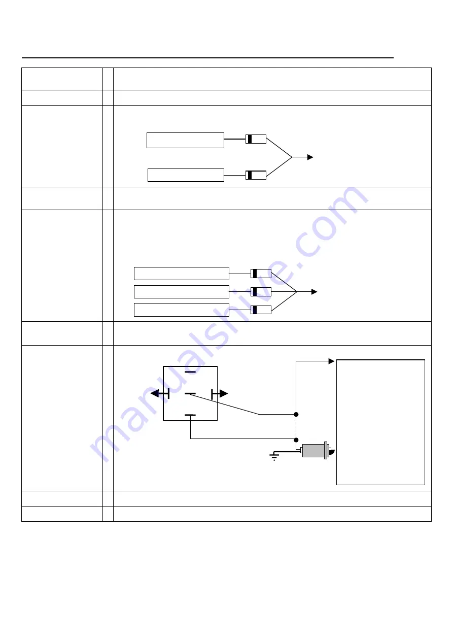
Parking Light Flash Wire (Positive Output 10Amp max).
Connect to the parking light circuit of the vehicle.
Note: If you wish to flash the indicators instead of the parking lights, you will need to wire 2 x 3 Amp Power
Diodes as shown:
BROWN
-
Ignition Input.
The ignition wire is usually located under the steering column of the vehicle.
This wire must be
+12V only when the vehicles keyswitch is at the ignition position, and must not fall to 0 volt when
the
engine is cranked.
ORANGE
-
Negative Trigger Input.
Connect to existing door switches, bonnet switch, or negative trigger wire from
optional ultrasonics or microwave sensor.
Please note:
only negative for switching doors. If positive door
switching - must use relays to reverse to negative - see diagram on page 9 of this manual. If you a using more
than one trigger device i.e. doors, bonnet, and impact sensor, then the 1 Amp Diodes supplied must be used
on each wire coming from each trigger input i.e.
BLUE
-
Negative LED Output.
Connect to the blue wire from the LED supplied. (Connect Red wire from LED to
+12VDC).
WHITE
-
Negative on Arm.
This wire enables an effective engine immobilisation circuit to be configured with this
alarm. Use optional 40amp Changeover Relay as shown:
YELLOW
-
Negative Pulse Lock Signal.
Refer to diagrams contained later in this manual for connection options.
GREY
-
Negative Pulse Unlock Signal.
Refer to diagrams contained later in this manual for connection options.
87a
87
86
85
30
Ignition
White
The starter wire is usually
located under the steering
column of the vehicle.
This
wire must be +12 Volts only
when the vehicle is
being
started
. Cut this wire. The
vehicle should not start. Solder
the starter motor side
to
number
30
on the relay. Solder
the other end to number
87
on
the relay. Disable only starter
motor
or
fuel pump.
Under no circumstances
should you cut the vehicle’s
main ignition system.
Left Indicator Circuit
Right Indicator Circuit
Green Wire from GXa Alarm
3 Amp Diodes
Impact Sensor Neg . Trigger Out
Negative Door Switch
Negative Bonnet Switch
Orange Wire from GXa Alarm
1 Amp Diodes