background image

eleCTrICal ConneCTIons

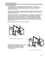
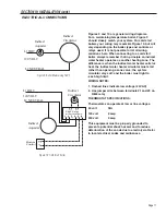
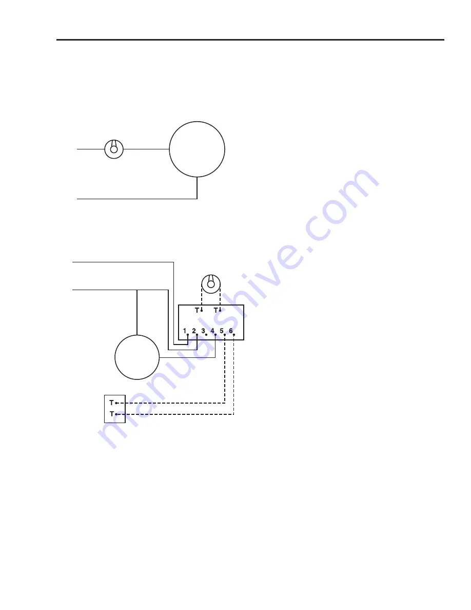
Figures 9 and 10 are general wiring diagrams.  
For a maintaining temperature boiler, Figure 9 
should closely match your system. For cold start 
boilers your wiring may resemble Figure 10, but will 
vary depending on the boiler type and controls or 
 relays used. It is not possible to list all wiring 
 variations here. When connecting to a cold start 
boiler, always remember that in principle an indirect 
water heater operates as another heating zone. The 
 difference is when the indirect water heater calls for 
heat, the indirect water heater circulator must start 
rather than opening a zone valve; the system 
circulator stays off; and the boiler must light to 

reach high limit.

WIRING NOTES:

1.   Dashed lines indicate low voltage (24 VAC)

2.   Use jumper wire between terminals #1 and #3 on 

R845 relay

THERMOSTAT SPECIFICATIONS:

Thermostats can operate at low or line voltages.

24 volt   

N/A

120 volt 

8 amp

240 volt 

5 amp

This equipment must be properly grounded to 
 prevent a potential shock hazard, and to reduce 
deterioration of the anode due to electrolysis. Refer 
to local electrical codes and ordinances.


Page 11

SECTION IV: INSTALLATION (cont .)

Figure 9: Boiler Maintaining 180°F

Figure 10: Cold Start Boiler

Figure 9:  Boiler Maintaining 180°F

Indirect

Aquastat

Indirect

Circulator

L1 HOT

120 VOLT

L2 NEUTRAL

Figure 10: Cold Start Boiler

L1 HOT

120 VOLT

L2 NEUTRAL

Indirect

Circulator

Indirect

Aquastat

Burner

Control

R845 Relay

or Equivalent

Содержание STID120

Страница 1: ...g the indirect water heater into service This unit must be installed by licensed or authorized installers or technical personnel that service water heating equipment The indirect water heater must be installed in accordance with all local codes and ordinances These instructions are a guide for the correct installation of the indirect water heater The manufacturer will not be liable for damages cau...

Страница 2: ...S Section I Specifications 3 Section II General Informations 5 Section III Pre Installation 7 Section IV Installation 9 Section V Maintenance 12 Section VI Troubleshooting 13 Section VII Parts List 14 Section VIII Warranty 15 ...

Страница 3: ...rature setting for normal residential use is 120 F Rheem recommends a tempering valve or anti scald valve be installed and used according to the manufacturer s directions to prevent scalding STID30 22 35 1 4 27 3 4 19 1 2 11 3 4 6 1 2 4 1 2 n a STID40 22 42 1 4 34 3 4 31 1 2 16 3 4 6 1 2 4 1 2 n a STID50 22 48 1 4 39 3 4 31 1 2 16 3 4 6 1 2 4 1 2 n a STID80 24 64 57 1 8 33 19 1 4 8 5 5 STID120 28 ...

Страница 4: ... r H e a t S o u r c e F r i c t i o n L o s s f t w c Table 2 Capacity Performance C a p a c i t i e s Section I Specifications cont NOTES First Hour Rating First Draw Continuous Draw Coil Input temperature flow rate Ratings based on 77 F rise with 58 F inlet potable water All data obtained through testing in accordance with GAMA INDIRECT FIRED WATER HEATER TESTING STANDARD IWH TS 1_MARCH 2003 ST...

Страница 5: ...mited control for domestic hot water temperature The proper temperature setting for domestic hot water use is 120 F 49 C If hotter water is required a tempering device or anti scald device must be installed at the domestic hot water outlet of the indirect water heater or at the point of use CAUTION Hot water in excess of 120 F can cause scalding Rheem recommends a tempering valve or anti scald val...

Страница 6: ...ater system When hydrogen is present there will probably be an unusual sound such as air escaping through the pipe as the water begins to flow There should be no smoking or open flame near the faucet at the time it is open UL 174 Temperature and pressure relief valve t P The T P valve is factory installed A discharge drain tube must be installed responsibility of the installer and shall terminate ...

Страница 7: ...0 F and 200 F boiler water To determine the appropriate circulator for your system follow these three steps 1 Calculate the pressure drop of all straight pipe and fittings on the supply and return at the desired flow rate 2 Add the pressure drop from Step 1 to the pressure drop through the indirect water heater coil see Table 2 for friction loss to obtain a total pressure drop 3 Select a circulato...

Страница 8: ...nimum coil output assume coil output boiler output listed in Tables 2 and 3 is not met the output first hour rating of the indirect water heater will not be met at the selected flow rate To approximate the reduction in first hour rating as a result of low boiler capacity use the following formula New first hour rating First hour rating Actual boiler output Minimum coil output For example the first...

Страница 9: ...d be minimized A flow check valve must be installed on the return line All piping to the inlet cold and outlet hot domestic water connections should be new copper with a minimum size of 1 2 ID for models STID30 STID40 and STID50 Use 3 4 ID minimum for models STID80 and STID120 All piping should conform to local codes and ordinances At a minimum refer to ILHR 84 code if local codes are not in place...

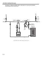
Страница 10: ...ation cont CHECK VALVES ZONE CIRCULATORS ISOLATION VALVES ADDITIONAL ZONES INDIRECT CIRCULATOR INDIRECT WATER HEATER TO HEATING ZONE AIR SEPARATOR AIR VENT EXPANSION TANK COLD WATER INLET BOILER CIRCULATOR LESS THAN 4 PIPE DIAMETERS BOILER FROM HEATING ZONE ISOLATION VALVES ADDITIONAL ZONES Figure 8 Rheem Indirect Water Heater with Low Mass Boiler ...

Страница 11: ...em circulator stays off and the boiler must light to reach high limit WIRING NOTES 1 Dashed lines indicate low voltage 24 VAC 2 Use jumper wire between terminals 1 and 3 on R845 relay THERMOSTAT SPECIFICATIONS Thermostats can operate at low or line voltages 24 volt N A 120 volt 8 amp 240 volt 5 amp This equipment must be properly grounded to prevent a potential shock hazard and to reduce deteriora...

Страница 12: ...and at least yearly once a time interval for inspection has been developed It is recommended to check the rod s six months after the heater is installed If the anode rod had reduced in size by two thirds of its original diameter of 3 4 or shows signs of pitting it is time for replacement Take the following steps when changing the anode rod s 1 Shut off water supply 2 Open any faucet to relieve tan...

Страница 13: ...KHFN SRZHU VXSSO 5HSODFH DV QHFHVVDU DXOW WDQN DTXDVWDW 5HSODFH DTXDVWDW RLOHU F FOHV PRUH WKDQ WLPHV SHU GD GXULQJ KRWHVW PRQWKV FHVVLYH GHPDQG 5HGXFH GHPDQG RU FRQVLGHU ODUJHU WDQN DXOW DTXDVWDW 5HSODFH DTXDVWDW RLOHU KLJK OLPLW VHW WRR ORZ QFUHDVH ERLOHU KLJK OLPLW VHWWLQJ QVXIILFLHQW KRW ZDWHU 5XVW VWDLQLQJ EDG WDVWH DQG RGRU LQ ZDWHU URQ PLQHUDOV LQ ZDWHU VXSSO LOWUDWLRQ 6FDOH KDUG ZKLWH SDUW...

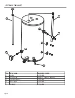
Страница 14: ...on VIi parts list No Description Applicable Models 1 Anode All models 2 Anode Outlet STID 30 STID 40 STID 50 3 T P Relief Valve All models 4 Drain Valve All models 5 Aquastat All models Page 14 14 2 1 3 4 5 ...

Страница 15: ...temperatures exceeding the maximum setting of the operating or high limit control l tank failures caused by operating the indirect water heater when it is not supplied with potable water free to circulate at all times m Damages malfunctions or failures caused by subjecting the tank to pressures greater than those shown on the rating label n Damages malfunctions or failures resulting from the use o...

Страница 16: ...arranty given by the rheem Water heater operation of rheem manufacturing company rheem for this indirect water heater no one is authorized to make any other warranties on behalf of rheem anY implieD WarrantieS incluDinG merchantabilitY or fitneSS for a particular purpoSe Shall not eXtenD beYonD the applicable WarrantY perioDS SpecifieD preViouSlY rheem S Sole liabilitY With reSpect to anY Defect S...

Отзывы: