


24
!"#
$"!%&
!"%
$"!'&
!"(
$"!)&
!"*
$"#!&
!"'
$"#%&
!"+
$"#'&
!")
$"#)&
!",
$"#-&
!"-
$"%%
./0
+,+
$(%*&
+(*
$%--&
',%
$%)'&
'(!
$%'!&
12345/0
)%(
$(*#&
+,,
$(%'&
+#)
$%-#&
'+)
$%+,&
'#%
$%*%&
*'-
$%#)&
123
)*,
$('(&
+-)
$(%-&
+*,
$(!+&
'-)
$%,%&
'*,
$%'-&
*-#
$%(%&
**'
$%#!&
12346786
-%%
$*('&
,,'
$*#,&
,*-
$*!#&
,##
$(,(&
))'
$(++&
)((
$(*+&
+-'
$(%,&
+**
$(!*&
+*'
$(!*&
9786
-*!
$***&
-#)
$*((&
,)'
$*#(&
,(,
$(-'&
)--
$())&
)+!
$('-&
)#+
$((,&
+)(
$(#,&
+%,
$%-+&
./0
+*+
$(!'&
',%
$%)'&
'#)
$%**&
*(+
$%!+&
12345/0
-,*
$*+*&
-()
$**%&
,-*
$*%%&
,*+
$(--&
)-,
$())&
)')
$(')&
)#!
$(('&
123
#!() $*,-&
--'
$*)!&
-'(
$*'!&
-#!
$*%-&
,+,
$*#!&
,%#
$(,)&
),#
$(+-&
)()
$(*,&
12346786
##+# $'*,& #!%! $*,#& #!), $'!-& #!*! $*-#&
---
$*)#&
-+(
$*'*&
-%!
$*(*&
,)(
$*#%&
)'(
$(''&
9786
#(-) $+'-& #('* $+(-& #(%# $+%(& #%)- $+!*& #%(, $',*& ##-( $'+(& ##') $'*+& #!+, $'!*&
-'+
$*'#&
./0
,#'
$(,'&
)+'
$(+#&
)#'
$(()&
++'
$(#*&
+#*
$%-!&
'',
$%+(&
'#*
$%*(&
12345/0
#%,* $+!+& #%(( $',%& ##), $''+& ##%- $'((& #!)! $'!'&
---
$*)#&
-%)
$*()&
,)+
$*#(&
,%(
$(,,&
123
#*#- $+)!& #()( $+*,& #(%( $+%*& #%,% $+!'& #%%, $',!& ##,! $'')& ##%- $'((& #!'* $*-)&
-,#
$*+(&
12346786
#*,' $)!#& #*'% $+,'& #*#, $++-& #(,+ $+'*& #(*+ $+('& #(#( $+%!& #%)% $+!!& #%%% $'))& ##-' $'+*&
9786
#)*' $,%*& #)%% $,#(& #+-% $)--& #++* $),'& #+(! $)+-& #'-- $)''& #'++ $)(-& #'!* $)#!& #('+ $+*!&
./0
#!** $*-(&
-'(
$*'!&
,+)
$*!-&
)+)
$(+%&
++)
$(#'&
')-
$%)(&
'!#
$%(+&
12345/0
#!#! $*))&
-)!
$*',&
-(+
$**%&
-!%
$*%+&
,+)
$*!-&
,(%
$(-(&
)-,
$())&
)++
$(+%&
)%'
$(*%&
123
#%*) $',-& ##,( $'',& ##%# $'%-& #!+* $'!%&
---
$*)#&
-((
$**!&
,+*
$*!,&
)-)
$()+&
)('
$(*)&
12346786
#,(* $,++& #)+, $,(*& #+-) $,!#& #+(- $))*& #',' $)*,& #'(- $)%+& #*), $+-,& #*%) $+)(& #()! $+*)&
9786
%!!, $-*,& #-'+ $-%(& #-!' $,--& #,** $,)!& #,!% $,'!& #)'! $,%+& #+-, $,!#& #+'' $),#& #+!* $)')&
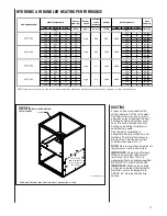
:5/02;<=2;>/;?@A2<B2@CD;23<07E6/DE<>75E2;<7?<=5@A2
4
4
4
FG#H#!I+!%*JII
##<K<##<<<<<<<<<<<<
$%)-<K<%)-&
(L*<<$''-&
4
4
FG#H!,I*,%#JII
#!<K<#!<<<<<<<<<<<<<
$%'*<K<%'*&
(L*<<$''-&
4
4
FG#H!+I(+#)JII
#!<K<,<<<<<<<<<<
$%'*<K<%!(&
#L%<<$()(&
4
4
4
4
4
4
4
4
4
4
4
4
4
FG#H!*I%*#*JII
#!<K<+<<<<<<<<<<<<
$%'*<K<#'%&
#L(<$%*,&
4
4
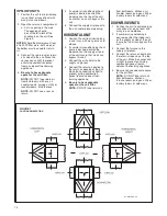
!"#$%&'()*'$)!*&#+,$)*'$)-+%.)/,$-%$0*&(,)1),(!%)2,(!)0%#,+3
1/325
:5/02;<M7N2<7?<<
$BB&
1/E/;<9O<<
$G@EE&
:5/02;<M=223
(-0)4+567)*89)#:;8<:9=)),>?:9@A;)3?A?8B)/9:66C9:)'@BD:6).A?:9)(E;CF@)4G/A7
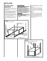
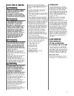
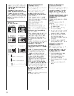
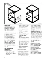
DIRECT DRIVE
INSTRUCTIONS FOR
CHANGING BLOWER SPEED
DISCONNECT THE ELECTRICAL
SUPPLY TO THE AIR HANDLER
BEFORE ATTEMPTING TO
CHANGE THE BLOWER SPEED.
FAILURE TO DO SO CAN CAUSE
ELECTRICAL SHOCk RESULTING
IN PERSONAL INJURY OR DEATH.
The blower motor must be wired for
blower speeds required for normal
operation.
If additional blower speed taps are
available (leads connected to “M1” and
“M2” on the electronic control), speeds
may be changed if necessary to fit
requirements of the particular
installation. Reconnect the unused
motor leads to “M1” or “M2.” Check
motor lead color for speed designation.
!
WARNING
TABLE 2
Heating speeds should not be
reduced where it could cause the air
handler air temperature rise to
exceed the maximum outlet air
temperature specified for the unit.
IMPORTANT:
Always check air
temperature rise after changing the
heating speed for any reason.
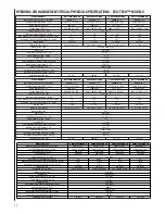
HYDRONIC AIR HANDLER AIR FLOW PERFORMANCE -PSC MODELS
Model
Blower Size
in [mm]
Motor HP
[Watt]
Blower Speed
RW1P04A2414NAA
10 X 6
[254 X 152]
1/5 [93]
RW1P06A3617NAA
10 X 8
[254 X 203]
1/2 [373]
RW1P08A4821NAA
10 X 10
[254 X 254]
1/2 [373]
RW1P10A4821NAA
11 X 11
[279 X 279]
3/4 [559]
0.1 [.02]
0.2 [.05]
0.3 [.07]
0.4 [.10] 0.5 [.12] 0.6
[.15] 0.7 [.17] 0.8 [.17]
0.9 [.22]
CFM [L/s] Air Delivery External Static Pressure Inches Water Column [kPa]
Low
642 [339] 612 [322] 591 [311] 524 [273]
—
—
—
—
—
Med-low
711 [377] 684 [362 655 [346] 624 [329] 578 [303] 526 [274]
—
—
—
Med-high
890 [477] 853 [456] 821 [438] 786 [419] 744 [396] 694 [368] 633 [334] 549 [287]
—
High
950 [510] 917 [492] 880 [471] 843 [451] 803 [428] 752 [400] 689 [365] 690 [366] 604 [318]
Low
900 [482] 882 [472] 865 [463] 843 [451] 806 [430] 759 [404] 687 [364] 617 [325]
—
Med-low
1135 [613] 1101 [594] 1073 [578] 1050 [566] 1012 [544] 960 [516] 889 [476] 801 [427] 700 [371]
Med-high
1260 [682] 1231 [666] 1199 [648] 1154 [623] 1113 [601] 1060 [571] 978 [526] 895 [479] 767 [408]
High
1397 [758] 1363 [739] 1314 [712] 1268 [687] 1209 [654] 1148 [620] 1077 [581] 980 [527] 829 [443]
Low
947 [508] 943 [506] 940 [504] 926 [497] 897 [481] 857 [458] 784 [418] 711 [377]
—
Med-low
1200 [649] 1193 [645] 1183 [639] 1163 [628] 1137 [614] 1084 [584] 1025 [552] 917 [492] 769 [409]
Med-high
1493 [812] 1481 [805] 1452 [789] 1411 [766] 1365 [741] 1220 [660] 1124 [607] 957 [514]
—
High
1865 [1018] 1810 [988] 1737 [947] 1671 [911] 1608 [876] 1533 [834] 1457 [792] 1292 [700] 1135 [613]
Low
904 [484] 875 [468] 845 [452] 798 [426] 735 [391] 688 [364] 643 [339] 593 [312] 539 [282]
Med-low
1189 [643] 1165 [629] 1114 [601] 1092 [589] 1057 [569] 1005 [541] 947 [508] 879 [471] 821 [438]
Med-high
1326 [719] 1304 [707] 1286 [697] 1266 [686] 1244 [673] 1217 [658] 1189 [643] 1140 [616] 1060 [571]
High
1970 [1077] 1951 [1066] 1937 [1058] 1926 [1052] 1895 [1035] 1865 [1018] 1759 [959] 1673 [912] 1624 [884]
Blower performance measured without filter in place.
!"#
$"!%&
!"%
$"!'&
!"(
$"!)&
!"*
$"#!&
!"'
$"#%&
!"+
$"#'&
!")
$"#)&
!",
$"#)&
!"-
$"%%&
./0
%'(
##-
%*!
##(
%%(
#!'
#--
-*
#,%
,+
#)(
,%
#+#
)+
123
123
123
123
4567./0
'#,
%**
'%!
%*'
'##
%*#
'!-
%*!
'!!
%(+
*-,
%('
*-+
%(*
*,!
%%)
*)(
%%(
456789:;
+'%
(!,
+'(
(!,
+',
(##
+',
(##
+'#
(!)
+*,
(!+
+**
(!*
+(*
%--
+%*
%-*
89:;
-!'
*%)
-#+
*(%
-##
*(!
-%%
*('
-#(
*(#
-#+
*(%
-##
*(!
-!*
*%)
,-%
*%#
./0
*!!
#,-
*##
#-*
*(%
%!*
*%%
#--
*##
#-*
*#%
#-*
(,#
#,!
(,!
#)-
()'
#))
4567./0
)*'
('%
))!
(+(
))+
(++
))!
(+(
),'
()!
),*
()!
),!
(+,
))'
(++
))!
(+(
456789:;
--!
*+)
#!#(
*),
#!*'
*-(
#!*!
*-#
#!',
*--
#!'%
*-+
#!'(
*-)
#!'!
*-+
#!*'
*-(
89:;
#%'%
'-#
#%+*
'-)
#%)-
+!*
#%),
+!(
#%,+
+!)
#%,'
+!+
#%,'
+!+
#%)'
+!%
#%)!
'--
./0
')+
%)%
''-
%+*
'(,
%'*
'#,
%**
*-,
%('
*)(
%%(
*''
%#'
*('
%!'
*#'
#-+
4567./0
,-,
*%*
-#%
*(!
-%-
*(,
-(%
**!
-!%
*%+
-!#
*%'
,,!
*#'
,+(
*!)
,*+
(--
456789:;
#(#,
+%%
#(*'
+('
#()(
+*,
#()+
+*-
#()'
+*-
#())
+'!
#(+,
+*+
#(')
+*!
#%-)
+#%
89:;
#+#'
)+%
#+#*
)+%
#+#,
)+*
#+!(
)')
#+!(
)')
#'-%
)'#
#',,
)*-
#')*
)*(
#'%'
)%!
./0
,##
(,(
)-+
()+
)+*
(+#
)!)
((*
+))
(%!
+''
(!-
+((
%--
+%!
%-(
+#!
%,,
4567./0
---
*)#
--+
*)!
--+
*)!
--#
*+,
-,%
*+(
-+(
*'*
-('
**#
-!'
*%)
,)%
*#%
456789:;
#'(*
)%*
#'%*
)#-
#'(-
)%+
#''+
)(*
#''!
)(%
#'*)
)(!
#'*(
)%,
#'((
)%(
#'(%
)%(
89:;
#)-'
,*)
#)-,
,*-
#,!!
,'!
#,!#
,'!
#,!*
,'#
#)-%
,*+
#),*
,*%
#))%
,(+
#)'(
,%)
8<=>?1@AB3@>B831=.C>B3@>BD.?EBFC>D?>431ACB7CA4B4?=C.G
4/65H
IH/05JBG9K5B9LB$MM&
4/N/JB8FB$EONN&
IH/05JBGP556
AD4B$.2Q&B39JB=5H9R5JSBCTN5JLOHBGNON9UBFJ5QQVJ5B@LU;5QBEON5JBA/HVMLB$WFO&
>E4X!+3(+#)133
#!BYB,B$%'*BYB%!(&
#2%B$(!*&
>E4X!*3%*#*133
#!BYB+B$%'*BYB#'%&
#2(B$#,!&
(2*B$*+'&
#!Y#!B$%'*Y%'*&
>E4X!,3*,%#133
>E4X#!3*,%#133
##BYB##B$%)-BYB%)-&
(2*B$'%!&
Содержание RW1P
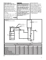
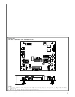
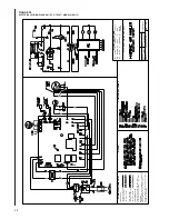
Страница 29: ...29 FIGURE 21 ELECTRICAL WIRING DIAGRAM PSC MOTORS RW1P...
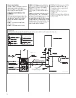
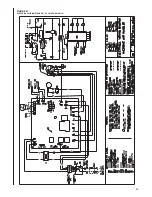
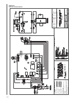
Страница 32: ...32 FIGURE 24 ELECTRICAL WIRING DIAGRAM...
Страница 33: ...33...
Страница 34: ...34...
Страница 35: ...35...
Страница 36: ...36 CM 0617...


