Rheem RW1P Скачать руководство пользователя страница 1

92-24161-150-04

SUPERSEDES 92-24161-150-03

INSTALLATION INSTRUCTIONS

HYDRONIC AIR HANDLER

RW1T/RW1P/RWMV

ISO 9001:2008

Содержание RW1P

Страница 1: ...92 24161 150 04 SUPERSEDES 92 24161 150 03 INSTALLATION INSTRUCTIONS HYDRONIC AIR HANDLER RW1T RW1P RWMV ISO 9001 2008...

Страница 2: ...N MAY RESULT IN PERSONAL INJURY SHEET METAL PARTS MAY HAVE SHARP EDGES OR BURRS USE CARE AND WEAR APPROPRIATE PROTECTIVE CLOTHING CAUTION NOTICE SAFETY INFORMATION WHEN AN AIR HANDLER IS INSTALLED SO...

Страница 3: ...nown to the State of California to cause cancer or birth defects such as fiberglass insulation lead in brass and combustion products from natural gas All new equipment shipped for sale in California w...

Страница 4: ...ERTIFIED BY UL 1 DOOR SWITCH 2 JUNCTION BOX 3 TRANSFORMERS 4 CAPACITORS 5 LOW VOLTAGE THERMOSTAT TERMINAL 6 BLOWER 7 PUMP IF REQUIRED 8 WATER INLET OUTLET FOR 14 HAH 9 WATER OUTLET INLET FOR 14 HAH 10...

Страница 5: ...UL 1 DOOR SWITCH 2 JUNCTION BOX 3 TRANSFORMERS 4 TERMINAL BLOCK 5 CONTROLBOARD 6 BLOWER 7 PUMP IF REQUIRED 8 WATER INLET OUTLET FOR 14 HAH 9 WATER OUTLET INLET FOR 14 HAH 10 BLOWER MOTOR 11 HYDRONIC C...

Страница 6: ...SEALED TO PREVENT DEPRESSURIZATION OF THE SPACE AND POSSIBLE MIGRATION OF COMBUSTION BYPRODUCTS INCLUDING CARBON MONOXIDE INTO THE LIVING SPACE IMPROPER INSTALLATION OR INSTALLATION NOT MADE IN ACCORD...

Страница 7: ...TY The design of air handlers with input ratings as listed in the tables under Figure 4 are certified by UL for the clearances to combustible materials shown in inches See name rating plate and cleara...

Страница 8: ...SIDE OPTIONAL RETURN AIR CUTOUT EITHER SIDE A I R F L O W A B C REF D E F G H ST A1242 03 X0 Model A B C D E F RW 04A2414 14 13 13 16 13 16 19 3 3 8 RW 06A3617 17 1 2 16 1 2 16 1 2 16 13 16 19 4 5 8...

Страница 9: ...llation Instructions and the Filter Pressure Drop Determine both static pressures at 1600 CFM Wet Coil Pressure Drop 0 3 in W C From Coil Manufacturer s Installation Instructions External Static Press...

Страница 10: ...x 8 254 x 203 10 x 10 254 x 254 11 x 11 279 x 279 Blower Motor Type EcoTech ECM Type Pump Type Wet Rotor Pump Power Supply V HZ PH 115 60 1 Pump Motor RLA LRA Amps 1 8 Pump HP W 1 8 86 Pump Maximum Wo...

Страница 11: ...ave a greater than normal resistance to air flow This can adversely affect air handler operation BE SURE TO CHECk AIR FLOW IMPORTANT When using outside air design and adjust the system to maintain a r...

Страница 12: ...s or runs with many turns and elbows 2 If summer air conditioning or heat pump is desired position the indoor coil on the supply air end of the unit Insure that no air can bypass this coil 3 Connect t...

Страница 13: ...nt Methods Using Straps Method 1 Use 4 8 x 3 4 sheet metal screws for each strap The straps should be vertical against the air handler sides and not pull away from the air handler sides Method 2 Fold...

Страница 14: ...present the piping should be supported immediately adjacent to the component On vertical runs copper tubing should be supported at each floor level or at a maximum of every 10 feet Thermal Expansion o...

Страница 15: ...an open loop system when configured to simultaneously deliver both domestic hot water and space heating By definition if the circuit is sealed off from the atmosphere at all locations as is true for m...

Страница 16: ...DV3 to which a hose MUST be connected and draining to a sink drain or outdoors STEP 4 CLOSE drain valves 1 2 DV1 and DV2 and OPEn ball valve 2 BV2 STEP 5 OPEn cold water supply main valve ball valve...

Страница 17: ...talled so that the electrical components are protected from water condensate Before proceeding with the electrical connections be certain that the voltage frequency and phase corresponds to that speci...

Страница 18: ...olt Wiring Factory 115 Volt Wiring Junction Box L1 L2 FIGURE 13 THERMOSTAT WIRING DIAGRAMS MODULATING AIR HANDLER W SINGLE STAGE A C FIRST STAGE HEAT COOL AUX HEATING FAN 24VAC HOT 24 VAC COMMON SINGL...

Страница 19: ...115 Volt Wiring Junction Box L1 L2 FIGURE 13A THERMOSTAT WIRING DIAGRAMS MODULATING AIR HANDLER W SINGLE STAGE A C FIRST STAGE HEAT COOL AUX HEATING FAN 24VAC HOT 24 VAC COMMON 24 VOLT SINGLE STAGE A...

Страница 20: ...ON MODULATING NOTES 1 For proper operation of an open loop system refer to Figures 11 and 17 the jumper shunt position on PCB point P7 should be in the FS position 2 When changing shunt position ensur...

Страница 21: ...BOARD MODULATING NOTES 1 For proper operation of an open loop system refer to Figures 11 and 17 the jumper shunt position on PCB point P7 should be in the FS position 2 When changing shunt position e...

Страница 22: ...Turn thermostat On and switch system to the heating mode The thermostat shall be set higher than the actual room temperature this will cause the circulator to energize and initiate the heating cycle I...

Страница 23: ...off the pump and go into a 5 minute delay If the supply temperature is adequate the main blower will then be energized and run for 30 seconds After the 30 second delay the control will monitor the sup...

Страница 24: ...6 15 0 7 17 0 8 17 0 9 22 CFM L s Air Delivery External Static Pressure Inches Water Column kPa Low 642 339 612 322 591 311 524 273 Med low 711 377 684 362 655 346 624 329 578 303 526 274 Med high 890...

Страница 25: ...ISCONNECT MAIN ELECTRICAL POWER TO THE UNIT BEFORE ATTEMPTING ANY MAINTE NANCE FAILURE TO DO SO CAN CAUSE ELECTRICAL SHOCk RESULTING IN PERSONAL INJURY OR DEATH WARNING DO NOT OPERATE THE SYSTEM FOR E...

Страница 26: ...induced draft blower motor must be cleaned periodically by a qualified installer service agency or the gas supplier to prevent the possibility of overheating due to an accumulation of dust and dirt on...

Страница 27: ...a d e z i s y l r e p o r p m I g n i t t e s p a t d e e p s r o t o m k c e h C w o l f r i a r o o d n i r e p o r p m I Call for domes c hot water air handler disabled un l call ends Unit is opera...

Страница 28: ...MANENTLY GROUNDED AND CONFORM TO I E C N E C C E C NATIONAL WIRING REGULATIONS AND LOCAL CODES AS APPLICABLE REPLACEMENT WIRE MUST BE THE SAME SIZE AND TYPE OF INSULATION AS ORIGINAL 105C MIN FIELD IN...

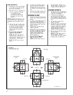
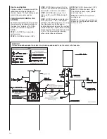
Страница 29: ...29 FIGURE 21 ELECTRICAL WIRING DIAGRAM PSC MOTORS RW1P...

Страница 30: ...RM TO I E C N E C C E C NATIONAL WIRI N G REGULATIONS AND LOC AL C ODES A S APPLICABLE R EPLACEMENT WIR E MUST BE THE SAME SIZE AND TYPE OF I NS ULATION AS ORIGINAL 105C MIN FIELD INS TALLED FACTOR Y...

Страница 31: ...C ONFORM TO I E C N E C C E C NATIONAL WIRI N G REGULATIONS AND LOC AL C ODES A S APPLICABLE R EPLACEMENT WIR E MUST BE THE SAME SIZE AND TYPE OF I NS ULATION AS ORIGINAL 105C MIN FIELD INS TALLED FAC...

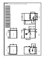
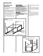
Страница 32: ...32 FIGURE 24 ELECTRICAL WIRING DIAGRAM...

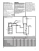
Страница 33: ...33...

Страница 34: ...34...

Страница 35: ...35...

Страница 36: ...36 CM 0617...

Отзывы: