


27
WIRING
WARNING:
Turn off electric power
at the fuse box or service panel before making
any electrical connections� Also, the ground
connection must be completed before making line
voltage connections� Failure to do so can result in
electrical shock, severe personal injury, or death�
Control Wiring
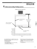
Running low-voltage wires in conduit with line
voltage power wires is not recommended� Low-
voltage wiring may be run through the insulated
plastic bushing provided in the 7/8" [19 mm]
hole in the base panel, up to and attached to
the pigtails from the bottom of the control box�
Conduit can be run to the base panel if desired by
removing the insulated bushing�
A thermostat and a 24-volt, 40 VA minimum
transformer are required for the control circuit
of the system� The furnace or the air handler
transformer may be used if sufficient� See the
wiring diagram for reference� Use “Wire Size” table
on this page to size the 24-volt control wiring�
Do not use phone cord to connect indoor and
outdoor units and thermostat� This could damage
the controls and may not be adequately sized for
the control’s electrical load�
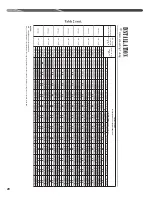
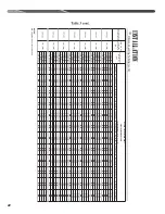
FIELD WIRE SIZE FOR 24-VOLT THERMOSTAT CIRCUITS
(1) Wire length equals twice the run distance�
NOTICE: Do not use control wiring smaller than No� 18
AWG between thermostat and outdoor unit�
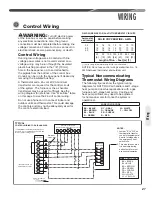
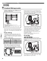
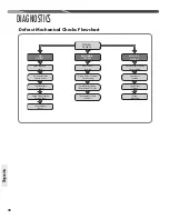
Typical Noncommunicating
Thermostat Wiring Diagrams
The following figures show the typical wiring
diagrams for RH1T; RHIV air handlers and 1-stage
heat pump and dual fuel applications with a gas
furnace and 1-stage heat pump� Cooling and
heat pump airflows may need to be adjusted
for homeowner comfort once the system is
operational�
Control Wiring
WIRE COLOR CODE
BK – BLACK GY – GRAY W – WHITE
BR – BROWN O – ORANGE Y – YELLOW
BL – BLUE PR – PURPLE
G – GREEN R – RED
B
W2
G
Y
W1
B
ODD
C
R
Air Handler
Y G
W2
E
Heat Pump Thermostat
Heat Pump
Outdoor Unit
C
R
Y
B
R
D
C
Y
Field Installed
Line Voltage
-
WIRING INFORMATION
Factory Standard
-
WH/BL
GR/BK
YL
WH/BK
GR/YL
BR
BL
RD
YL/BL
Optional Field Installed Jumper (see note 1)
1
*
*
* 2
*Not present on all
air-handler models.
OPTIONAL
- 1 STAGE HEAT
YL
BR
BL
RD
PR
NOTES:
1. Jumper “E” to “W2” on
thermostat to transfer
control of supplemental
heat to 1st stage when
the emergency heat
switch is on.
2. This wire turns on elec-
tric heat strip during
defrost, omit for most
economical operation.
WIRE COLOR CODE
BK = BLACK
BL = BLUE
BR = BROWN
GR = GREEN
PR = PURPLE
RD = RED
WH = WHITE
YL = YELLOW
*
*If maximum outlet temperature rise is
desired, it is recommended that W1 and
W2 be jumpered together.
TYPICAL
CONTROL WIRING FOR AIR HANDLER
Thermostat
Load (amps)
SOLID COPPER WIRE – AWG.
3.0 18 16 14 12 10 10 10
2.5 18 16 14 12 10 10 10
2.0 18 16 14 12 10 10 10
20 50 100 150 200 250 300
[6] [15] [30] [46] [51] [76] [91]
Length of Run – Feet [m] (1)
Wiring
Содержание RP1336AC1NA
Страница 48: ...48 FOR SINGLE PHASE WITH PSC FAN MOTORS WIRING DIAGRAMS Wiring Diagrams ...
Страница 49: ...49 Wiring Diagrams WIRING DIAGRAMS 3 PHASE 208 230V MODELS ...
Страница 50: ...50 Wiring Diagrams WIRING DIAGRAMS FOR 3 PHASE 460 575V ...
Страница 51: ...51 ...
Страница 52: ...52 CM 0215 ...


