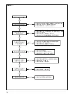
Rheem LX2000 Series Скачать руководство пользователя страница 20

20

CAUSE

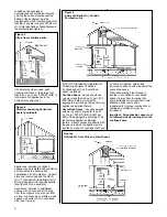
1. Roof peak or other surrounding

objects higher than chimney top.

2. Flue cap on chimney.

3. Coping smaller than chimney

interior.

4. Air leak from loose bricks or

mortar.

5. Inside dimensions of chimney are

too small.

6. Double chimney separation wall

leaks due to loose bricks or
mortar.

7. Joist protruding into chimney.

8. Brick, mortar or other obstruction

lodged in chimney.

9. Soot accumulation in offset.

10. Offset is too short.

11. More than one heating appliance

connected to same chimney flue.

12. Smoke pipe protrudes into chimney

or elbow too far.

13. Smoke pipe is loose fitting, too

long or has too many elbows.

14. Opening between chimney flues.

15. Loose fitting cleanout door.

16. New chimney.

17. Excessive draft..

CORRECTION

Extend chimney 24 inches above roof
and surrounding objects within 30 feet.

Remove.

Enlarge to match chimney interior.

Replace loose bricks and mortar.

If all other causes have been
eliminated a new chimney may have
to be built.

Replace loose bricks or mortar.

Remove.

Have chimney cleaned.

Clean out.

Straighten or lengthen offset.

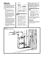
Furnace ideally should have its own
flue. If this is not possible, smoke pipe
should be connected as shown in
Figure 23.

Make flush with inside of chimney.

Cement joints, shorten and eliminate
elbows.

Seal openings permanently.

Seal openings, close door tightly.

Allow 2 to 4 weeks to dry.

Open barometric damper.

CORRECTION OF POOR CHIMNEY DRAFT CONDITIONS

FIGURE 24. CHIMNEY PROBLEMS
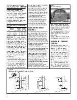
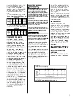
FIGURE 25.

Pipe pushed too far

inside elbow, as shown, interferes
with draft.

FIGURE 26.

If chimney ends only a

short distance below point where
flue enters, make a “toothpick joint”
as shown. Remove soot from below
regularly.

FIGURE 27.

If it is necessary to

connect more than one heating
appliance to the same chimney,
connect furnace flue pipe as “B.”
Connect lower BTU appliance pipe
as “A.”

Содержание LX2000 Series

Страница 1: ...cal switch do not use any phone in your building Immediately call your fuel oil supplier from a neighbor s phone Follow the fuel oil supplier s instructions If you cannot reach your fuel oil supplier...

Страница 2: ...und to electrical panel DC microamp A flame signal hot surface ignition units Correct control voltage Measure and set heat anticipator amperage Air conditioning low voltage wires connected to terminal...

Страница 3: ...rical Wiring 9 Thermostat 9 Heat Anticipator Settings 9 Typical Installation Diagrams 10 Operating Instructions 11 Lighting Instructions 11 Burner Adjustment 12 Furnace Adjustment 12 Air Volume Adjust...

Страница 4: ...N OR AGAINST THE FURNACE JACKET THE AREA AROUND THE FURNACE MUST BE KEPT CLEAR AND FREE OF ALL COMBUSTIBLE MATERIAL INCLUDING GASOLINE AND OTHER FLAMMABLE VAPOR OR LIQUIDS THE HOMEOWNER SHOULD BE CAUT...

Страница 5: ...hen they condense When appliances are installed within a confined space and combustion air is taken from within the heated space the air supply must be through two permanent openings of equal area one...

Страница 6: ...f Oil Burning Equipment defines confined space and unconfined space as follows Confined Space Any space whose volume is less than 50 cu ft per 1 000 BTU HR 4 8 M3 per KW of the aggregate input rating...

Страница 7: ...ct connection should be made to the bottom of the furnace For installations where return air ducts cannot be run under the floor return air may be taken from the sides and or back by cutting the furna...

Страница 8: ...elay is mounted to the unit s main junction box and the flame sensor cadmium sulfide cell is enclosed in the burner housing above the blower wheel The standard oil burner is equipped with a single sta...

Страница 9: ...ve should be installed in the suction line to keep the line primed and the internal by pass in the fuel unit must be plugged as per instructions furnished with the burner All oil lines must be tight a...

Страница 10: ...10 TYPICAL INSTALLATION DIAGRAMS FIGURE 9 TWO PIPE INSTALLATION FIGURE 10 ONE PIPE INSTALLATION...

Страница 11: ...r plastic hose over the bleed plug Loosen the plug and catch the oil in an empty container Tighten the plug when all air is purged 5 Reset room thermostat to desired temperature setting 11 WARNING TO...

Страница 12: ...ter from the barometric damper Another 1 4 inch hole is provided by the manufacturer for testing over the fire Drill another 1 4 hole between the barometric damper and the chimney as shown in Figure 1...

Страница 13: ...tion in this manual for more information Operating the unit at an excessive firing rate generates pollutant emissions Check for prompt pump cutoff by observing the flame or by checking for smoke at sh...

Страница 14: ...R CHECK FUEL SUPPLY NOZZLE CHECK CAD CELL PRIMARY CONTROL CHECK FAN CENTER CHECK BLOWER MOTOR WIRING CHECK BLOWER MOTOR CAPACITOR CHECK THERMOSTAT AND CONTROL WIRING CHECK ISOLATION RELAY CHECK PRIMAR...

Страница 15: ...rode tips see figure 17 2 Position the gauge so the center scribe mark is in line with the nozzle orifice Do not scratch the nozzle face 15 housing This locks the assembly into position The nozzle sho...

Страница 16: ...degrees E Compare the calculated tempera ture rise with the specified temperature rise on the rating plate TEMPERATURE RISE TOO HIGH Check for proper fan speed Check static pressure on duct system for...

Страница 17: ...duce the overfire draft dangerously TIPS FOR BETTER SMOKE READINGS 1 Before using tap the sampling tube to loosen any soot or rust tighten the clamp screw without any filter paper in the slot and purg...

Страница 18: ...r motor must be cleaned periodically by a qualified installer service agency or the oil supplier to prevent the possibility of overheating due to an accumulation of dust and dirt on the windings or on...

Страница 19: ...1375 649 1715 809 2070 977 620 293 835 394 940 444 1190 562 620 293 835 394 940 444 1190 562 620 293 835 394 940 444 1190 562 620 293 835 394 940 444 1190 562 620 293 865 408 1030 486 1290 609 1065 50...

Страница 20: ...ove Enlarge to match chimney interior Replace loose bricks and mortar If all other causes have been eliminated a new chimney may have to be built Replace loose bricks or mortar Remove Have chimney cle...

Страница 21: ...LY DATA 056 067 084 095 112 130 150 NOTE This appliance should only be used with specified Delavan or Monarch nozzles Use of other nozzles may result in unsatisfactory performance DELAVAN 50 60 70 B D...

Страница 22: ...to oil pump supply line 16 Burner blower air inlet restricted or burner blower wheel dirty 17 Restricted flue 1 Cracked dirty or loose electrodes 2 Electrodes not properly adjusted 3 Incorrect nozzle...

Страница 23: ...ion kit 3 Undersized return air 4 Overfired furnace 5 Dirty heat exchanger 6 High draft barometric damper not properly set 7 Excessive temperature rise 8 Air shutter adjustment open too much 1 Lack of...

Страница 24: ...in operating position 7 Dirty strainers 8 Dirty line filter 9 Motor does not come up to speed 10 Bad air leak at seal 11 Improper pump setting 1 Pump gears worn 2 Vertical oil lift too great over 10...

Страница 25: ...rfire Draft inches negative H2O Breech Draft inches negative H2O Chimney Draft inches negative H2O Smoke Reading CO2 CO2 Stack Temperature degrees F Room Temperature degrees F Net Stack Temperature de...

Страница 26: ...HEATING AND COOLING CONTINUOUS LOW SPEED BLOWER SCHEMATICFIGURE 38 FOR MODELS WITH UTEC 1012 925 INTEGRATED FURNACE CONTROL 26...

Страница 27: ...27 PARALLEL WIRING UPFLOW OIL FURNACES SCHEMATIC...

Страница 28: ...28 HEATING AND COOLING CONTINUOUS LOW SPEED BLOWER SCHEMATICFIGURE 38...

Страница 29: ...29 FIGURE 38 FOR MODELS WITH UTEC 1012 925 INTEGRATED FURNACE CONTROL...

Страница 30: ...30...

Страница 31: ...31...

Страница 32: ...32 CM 898...

Отзывы: