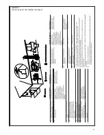

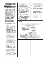

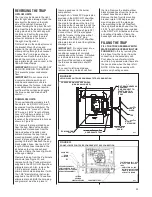

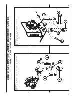


Refer to Figure 36 for Steps 6-11.
6. Locate the parts bag in the
burner compartment. Install two
plastic plugs
➅
in the side of the
jacket from bottom side up.
7. Attach the gasket
➇
onto the trap
assembly so that the gasket
holes on the gasket line up with
the holes on the trap assembly.
8. Fill the trap assembly
➆
with 1/2
cup of water.
9. Insert the trap assembly with
gasket up through the existing
hole in the jacket and secure
from inside the jacket. Use two
screws provided. Screw down
into the two “ears” molded into
either side of the trap. Snug the
trap assembly against the
furnace jacket compressing the
gasket slightly to eliminate any
air leaks. Do not overtighten!
10. Attach the black molded rubber
90° elbow
➂
to the straight spout
on the trap top using a white
nylon clamp
➂
. Attach the other
end of the rubber elbow to the
spout
➂
located on the exhaust
transition
➂
using a white nylon
clamp.
11. Attach the 90° end of the molded
hose
➂
to the collector box.
Clamp the hose tight with a white
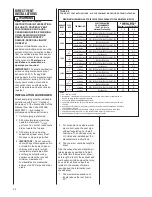
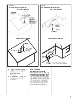
CONDENSATE DRAIN
FOR HORIZONTAL
INSTALLATION
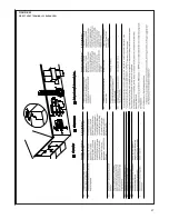
Refer to Figure 35 for Steps 1-5.
1. This unit is shipped factory ready
for downflow installation. The
condensate trap assembly and
drain hoses require conversion
for horizontal installation.
Remove the existing condensate
trap with the unit in the upright
position.
IMPORTANT:
This furnace may
only be installed so that when
facing the front of the furnace,
supply air is discharged on the
left hand side.
2. Remove the burner compartment
door from the unit.
3. Remove the two screws from the
right side of the furnace jacket
which support the trap mounting
bracket
➂
. Remove the two
plastic plugs on either side of the
trap outlet hole and discard.
4. Remove the black molded 90°
hose
➂
from the top of the
existing trap
➂
and from the
furnace collector box. Cut 1.0
inch from the long end of the
hose.
5. Remove the double-elbow black
molded hose
➂
from the exhaust
transition
➂
. Discard this hose
and the downflow trap. Retain
the clamps for future use.
Additional clamps are provided in
the parts bag if any clamps are
damaged during conversion
process.
NOTE:
The following steps should
take place with the furnace in the
horizontal position.
34
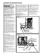
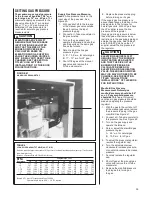
FIGURE 34
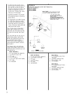
HORIZONTAL CONDENSATE DRAIN
I408
CONDENSATE TRAP
DRAIN LINE
NEUTRALIZER CARTRIDGE
(OPTIONAL)
TO FLOOR DRAIN OR CONDENSATE PUMP
NOTE:
SEE GENERAL NOTES FOR
HORIZONTAL MODELS
FOR PIPE HEIGHT.
OVERFLOW LINE
(REQUIRED ONLY WHEN
OPTIONAL NEUTRALIZER
CARTRIDGE IS USED.)
nylon clamp. Then attach the
long end of the molded hose to
the 45° elbow molded into the
top of the trap assembly. Clamp
the hose tight with white nylon
clamp.
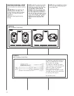
IMPORTANT:
Tighten all clamp
connections with a pair of pliers
and check for leaks after
conversion is complete.
11.
IMPORTANT:
There are two
options when choosing a height
for the condensate riser:
CONDENSATE OVERFLOW:
With a 1
3
⁄
4
inch riser installed
above the tee, a blocked drain
will result in overflow from the
riser.
FURNACE SHUTDOWN: To
cause the furnace to shut down
when a blocked drain is present,
install a riser which is a minimum
of 5
1
⁄
2
”. If the furnace is installed
in an attic, crawlspace or other
area where freezing
temperatures may occur, the
furnace drain can freeze while
shut off for long periods of time.
Use a solvent cement that is
compatible with PVC material.
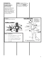
CONVERTING DOWNFLOW TO HORIZONTAL
C
A
D
B
E
F
G
H
L
I
J
K
E


