© Xiamen RGBlink Science & Technology Co., Ltd.
Ph: +86 592 5771197
| [email protected] | www.rgblink.com
14
Chapter 3 Use Your Product
3.1 Video Output
3.1.1 Power on initial configuration
The remote control receiving indicator flashes after power on, the pan-tilt turns left to the lowest left to the
lowest, and then turns to the HOME position (both the horizontal and vertical positions are in the middle), while
the movement first shrinks and then stretches. When remote control receiving indicator stops flashing, the
self-checking is completed. After power on and self-checking, the camera will automatically return to the preset 0
position if it
’
s pre-set.
3.1.2 Video Output
Connect to the video output cable: the user can refer to Figure 1.1 product interfaces.
USB2.0 output: Connect the camera with the computer USB2.0 interface (black), open the Device Manager to see
whether there is an imaging device and whether the Universal Serial Bus controllers recognize the USB2.0 device.
After properly identified, open the software, choose the imaging device, and then it will output the image.
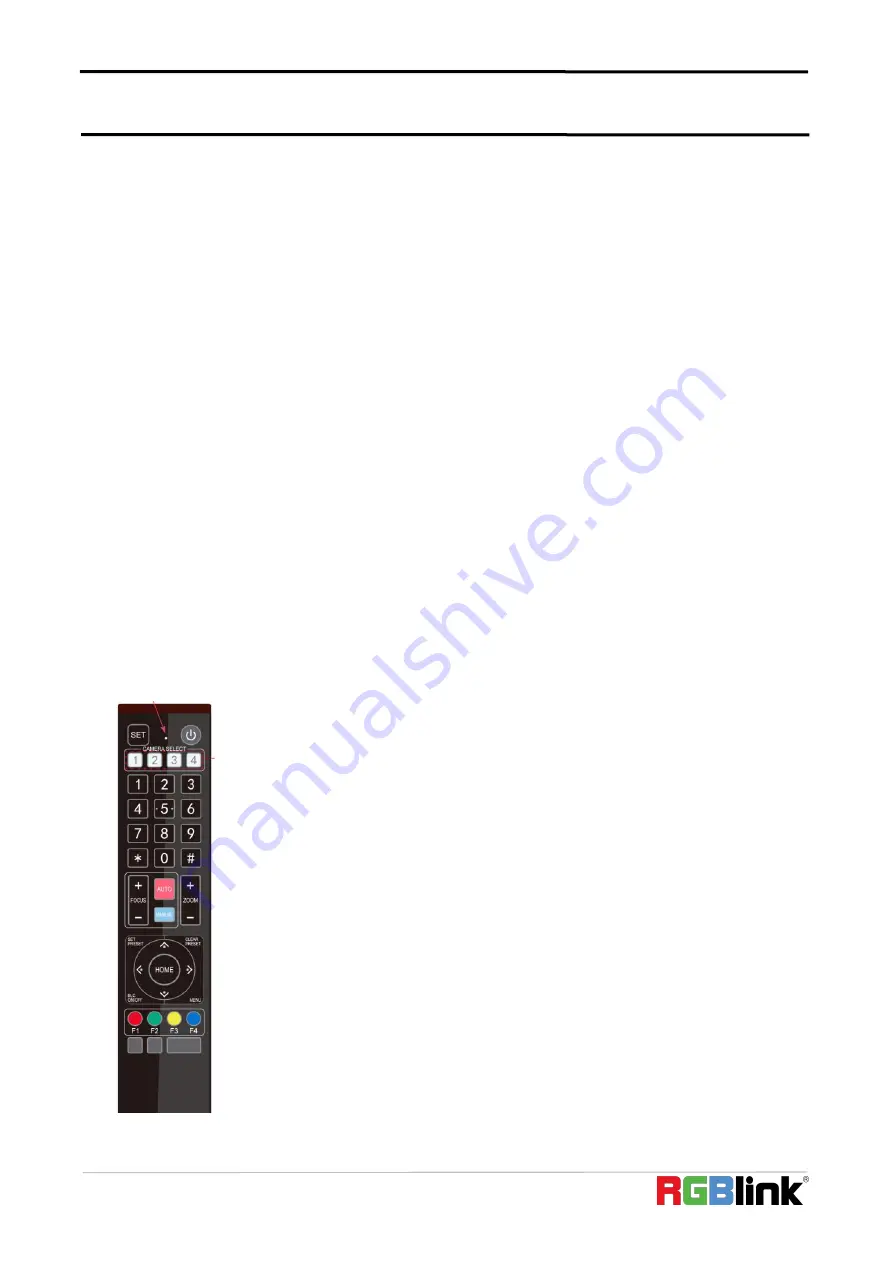
3.2 Remote Controller
3.2.1 Keys Instruction
1) In this manual,
“
press the key
”
means a click rather than a long-press, and a special
note will be given if a long-press for more than one second is required.
2) When a key-combination is required, do it in sequence. For example,
“
【
*
】
+
【
#
】
+
【
F1
】
”
means press
“
【
*
】
”
first and then press
“
【
#
】
”
and last press
“
【
F1
】
”
.
1. Standby Key
The camera enters standby mode if long press 3s on standby key;
Long press 3s again on the standby key, the camera will self-check again and return to
HOME position (If preset 0 position is set, the camera will return to preset 0 position).


