


C
HAPTER
2 - S
PECIFICATIONS
Antenna Specifications
8
XG2510HE M
ANAGER
H
ARDWARE
AND
C
ONFIGURATION
G
UIDE
Antenna Specifications
The antenna provided on the XG2510HE gateway/manager meets the specifications in
Table 8. For optimum performance, position the antenna vertically when gateway/
manager is installed.
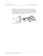
Power Supply
A universal power supply is included with each XG2510HE gateway/manager. The
output of the transformer is 12 V at 1.1 Amps DC, and it is connected to + (positive) and
-(ground) terminals of the connector. However, any DC supply with an output of 9 to 30
V at 0.5 Amps can be connected. A 24 VAC supply can be connected to the two right-
most terminals of the connector (see Figure 6). The power supply connector uses a
Phoenix PN 1757048 or equivalent mating connector.
Figure 6
Power Supply Connector
Table 8
XG2510HE Antenna Specifications
Parameter
Value
Frequency range
2.4-2.4835 GHz
Impedance
50
Ω
Gain
+2 dBi maximum
Pattern
Omni-directional
2 4 V A C
I n p u t P i n s
9 - 3 0 V D C
I n p u t P i n s
Содержание XG2510HE
Страница 1: ...RF Monolithics Inc XG2510HE Gateway Manager Hardware and Configuration Guide WirelessHART ...
Страница 2: ...XG2510HE MANAGER HARDWARE AND CONFIGURATION GUIDE ...
Страница 6: ...ABOUT THIS GUIDE iv XG2510HE MANAGER HARDWARE AND CONFIGURATION GUIDE ...
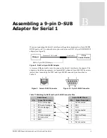
Страница 28: ...20 XG2510HE MANAGER HARDWARE AND CONFIGURATION GUIDE APPENDIX B ASSEMBLING A 9 PIN D SUB ADAPTER FOR SERIAL 1 ...


