


RFDMX User Manual
Page
4
of
12
–
Version 1.3
–
Status
–
DRAFT
Document Number
–
PRJ-TXP-MAN-001
Pin
Description
Rated voltage
DMX B/D -
DMX512 Stream signal inverted
0 - 5V
DMX A/D+
DMX512 Stream signal
0 - 5V
DMX GND
Ground
0
POWER GND Ground
0
POWER VIN
Supply Voltage
7
–
33V
The LED driver outputs can be connected when operating as receiver and are used to drive 4-channel
LED’s after decoding the DMX512 stream for the address set on the board.
The supply voltage must
high enough to drive the LED string if connected.
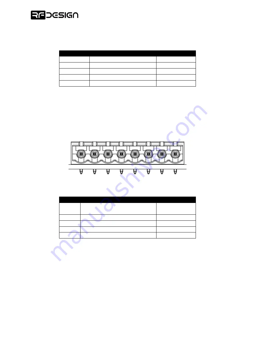
LED
1
(
-)
V
IN
(+)
LED
2
(-
)
VIN
(+)
LED
3
(
-)
VIN
(+)
LED
4
(
-)
VIN
(+)
LED output connector front view
Pin
Description
Rated voltage
VIN (+)
LED supply
–
connected to the
supply voltage VIN internally
7 - 33V
LED1 (-)
Open-drain LED output 1
0 - 33V
LED2 (-)
Open-drain LED output 2
0 - 33V
LED3 (-)
Open-drain LED output 3
0 - 33V
LED4 (-)
Open-drain LED output 4
0 - 33V
The board features a USB port which is used for firmware updates. No external power source is
required during the firmware upgrade as the USB provides enough energy to the embedded
microcontroller and long-range radio module.
The RP-SMA connectors should be connected to suitable antennas for required signal coverage,
although the system will work with any
50Ω impedance
element and the matching RP-SMA connector.
Only ANT1 is used for transmitter and receiver units. Do not use ANT2.