8
Installation
1
1
2
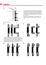
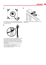
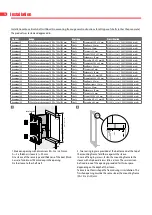
3. It is recommended that once the holes have been drilled at
the cable exit position, the cables are laid and clipped in posi-
tion around the inside perimeter of the damper framing and
each cable “Fed and Drawn” through these holes to the outside
of the damper spigot. At all times take care not to damage the
cable insulation.
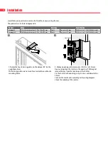
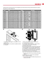
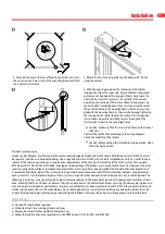
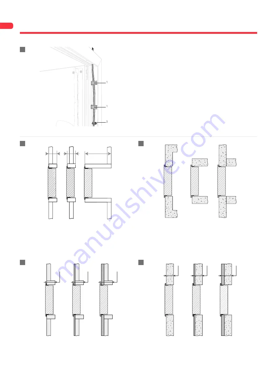
Lead the cables through the opening. Use the fixation clips
(1) and the plastic cable clamp (2) to attach the cables to the
frame.
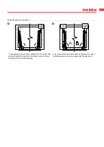
Position in the shaft
≥105
≥105
≥105
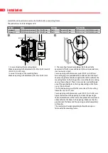
1. Smoke control dampers should be fitted to the smoke
evacuation shaft and / or fire resisting duct with a penetration
seal of a type used in the test of the damper to EN1366-10. They
may be installed within the duct or wall thickness of the fire
separating element or onto the surface of these elements or to
a fire resisting branch duct connecting to the shaft.
≥
105 mm
≥
105 mm
≥
105 mm
≥
70 mm
≥
70 mm
≥
70 mm
3
1
2
3
4


