RF-BM-2652P3
Shenzhen RF-star Technology Co., Ltd.
Page 10 of 20
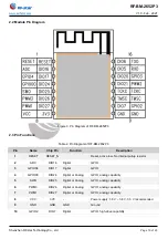
2.2 Module Pin Diagram
Figure 3. Pin Diagram of RF-BM-2652P3
2.3 Pin Functions
Table 2. Pin Diagram of RF-BM-2652P3
Pin
Name
Chip Pin
Function
Description
1
RESET
RESET_N
Reset, active low. No internal pullup resistor
2
ADC
DIO16
Digital
GPIO
3
GPIO04
DIO17
Digital
GPIO
4
GPIO00
DIO24
Digital or Analog
GPIO, analog capability
5
SWO
DIO25
Digital or Analog
GPIO, analog capability
6
PWM3
DIO26
Digital or Analog
GPIO, analog capability
7
PWM1
DIO27
Digital or Analog
GPIO, analog capability
8
VCC
3V3
-
Power supply: 1.8 V ~ 3.8 V, 3.3 V recommended.
9
GND
GND
GND
Ground
10
GPIO2
DIO7
Digital
GPIO, high-drive capability


