8-32
Motors
Rexroth EcoDrive Cs Drives
DOK-ECODR3-DKC**.3-CS*-PR02-EN-P
Bearings and Shaft Load
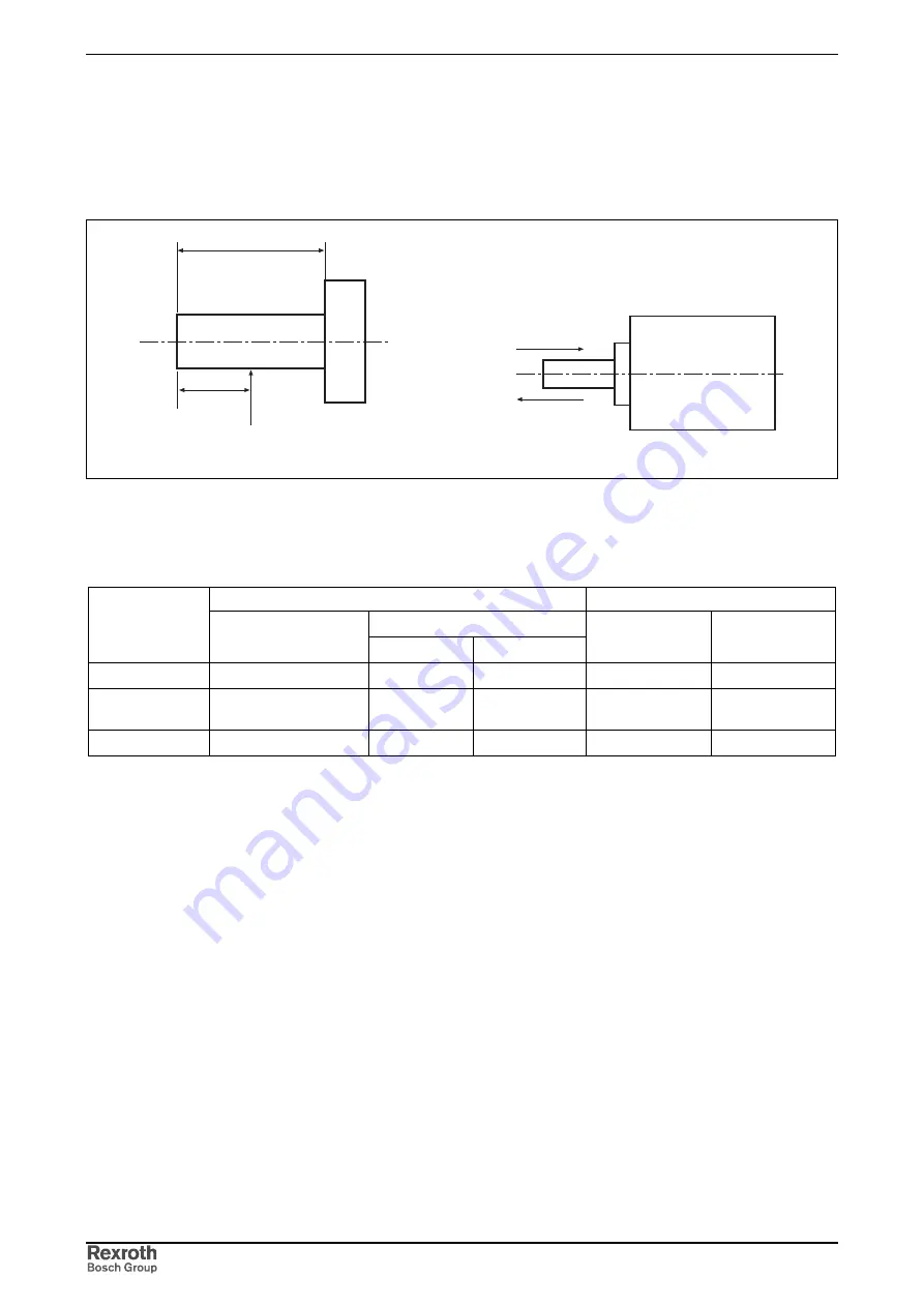
During operation, both radial and axial forces act upon the motor shaft
and the motor bearings. The construction of the machine and the
attachment of driving elements on the shaft side must be adjusted to one
another to ensure that the load limits specified are not exceeded.
wellenbelastung_radial.fh7
L
P
L/2
wellenbelastung_axial.fh7
A
M
B
L:
shaft length
P:
point of action of the radial force
A, B:
directions of the axial force
The following table shows the allowed shaft load of the individual motors.
During assembly
In operation
axial force
Motor
radial force
direction A
direction B
radial force
axial force
MSM020B
147
88.2
117.6
68.6
58.8
MSM030B;
MSM030C
392
147
196
245
98
MSM040B
686
294
392
392
147
all data in N
Fig. 8-43:
Allowed shaft load
The maximum permissible radial force F
radial_max
depends on the following
factors:
•
Shaft break load
•
Point of force application
•
Shaft design (plain; with keyway)
The permissible radial force F
radial
depends on the following factors:
•
Arithmetic mean speed (n
mean
)
•
Point of force application
•
Bearing service life
The maximum permissible axial force F
axial
is proportional to the radial
force. Please refer to the section entitled “Shaft load” in the technical data
for the proportionality factor.
Maximum permissible radial
force F
radial_max
Permissible radial force F
radial
Permissible axial force F
axial
Courtesy
of
CMA/Flodyne/Hydradyne
▪
Motion
Control
▪
Hydraulic
▪
Pneumatic
▪
Electrical
▪
Mechanical
▪
(800)
426-5480
▪
www.cmafh.com


