


Rexnord
378-206
3001 W. Canal St., Milwaukee, WI 53208-4200 USA
January 2019
Telephone:
414-342-3131
Fax:
414-937-4359
www.rexnord.com
Supersedes 07-15
(PN-212395)
Falk Quadrive Shaft-Mounted Drives Model A
•
Owners Manual
Sizes 5407-5608
(Page 17 of 53)
Section III
DRIVE REASSEMBLY
REFER TO PARTS DRAWING FIGURE 14.
1 .
GENERAL
a . Clean all parts to be reassembled and coat all taper
roller bearing cups and pinion teeth with oil . DO
NOT lubricate gear teeth prior to assembly on shaft .
b . Heat all tapered roller bearing cones in an oven to
275°F (135°C) .
CAUTION
: Do not apply flame directly to bearings
or rest bearings directly on a heated surface.
c . Slide or press all bearing cones tight against the
shaft shoulder or spacer .
CAUTION
: Do not apply force to the bearing cage or
rollers. Apply force against the cone only.
2 .
ASSEMBLY OF TAPERED ROLLER BEARING CUPS
— Where bearings will be reused and where bearing
cups were not removed from the housing, skip to
Step 3 . It is recommended that bearings be replaced
whenever drive is disassembled after being in service .
Install bearing cups only in housing base at this time .
Coat bearing cups and housing bores with an SAE
20 (or heavier) oil and drive or press cup squarely
into the housing bores until positioned as shown in
Figures 15 and 16 . Use a flat plate and a brass bar to
avoid damaging the bearing cups . NOTE: The exact
positioning of the bearings in the bores will be achieved
during the bearing adjustment procedure in Step 6 .
CAUTION
: Take care not to allow cups to cock during
their installation as this could result in permanent
damage to housing.
If cups become cocked in the bores, tap the high side
lightly to re-position .
3 . Assemble seal cages to housing output side(base) as
follows:
a . Turn housing onto its side being careful that the
bearing cups do not fall out of the bores . Assemble
low-speed seal cage without seal and one .015”
(0 .38 mm) shim-gasket, Ref . #11 or 12 and 24 . Cross
tighten fasteners, Ref . #34, to torque specified in
Table 14 .
Check to be sure that cages and covers are
registered on the bearing cups to avoid hanging up
of the cups .
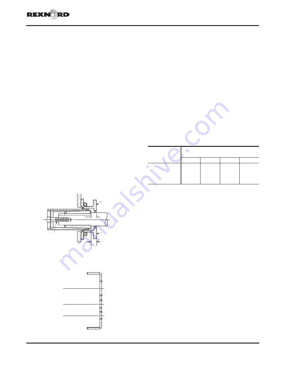
MOUNTING
SURFACE
U
MOUNTING
SUFACE
C
THRUST
PLATE
FASTENER
Figure 15
4A2
LOW-SPEED SHAFT
BEARING BORE
2A2
INTERMEDIATE
PINION BEARING BORE
1A2
HIGH-SPEED SHAFT
BEARING BORE
Figure 16
Table 14 — Fastener Tightening Torques
Location
Fastener Size — Inch
Tightening Torque — lb-ft (Nm)
.375-16
.500-13
.750-10
.875-9
Low-Speed Seal Cage
. . .
. . .
330 (447)
533 (723)
Intermediate End Cover 27.5 (37,3)
68.8 (93,2)
. . .
. . .
High-Speed Seal Cage/
End Cover
27.5 (37,3)
68.8 (93,2)
. . .
. . .
Housing Cover
. . .
68.8 (93,2)
245 (332)
. . .
c
Torques are for non-lubricated fasteners .
b . Assemble intermediate end cover and one .015”
(0 .38 mm) shim-gasket, Ref . #15 and 25 . Cross
tighten fasteners, Ref . #35, to torque specified in
Table 14 .
c . Assemble high-speed pinion shaft cover or seal
cage without seal as follows:
SIZES 5407-5608 WITHOUT BACKSTOP
—
Assemble shaft cover and one .015” (0 .38 mm)
shim-gasket, Ref . #17 and 27 . Cross tighten
fasteners, Ref . #37, to torque specified in Table 14 .
SIZES 5407 & 5415 WITH BACKSTOP
— Assemble
shaft cover, 1st .015” (0 .38 mm) shim-gasket,
backstop cage and 2nd .015” (0 .38 mm) shim-
gasket, Ref . #19, 20, 29 and 30 . Finger tighten
fasteners, Ref . #38 . NOTE: The backstop, Ref . #5A
will be added later .
SIZES 5507 & 5608 WITH EXTERNAL BACKSTOP
— Assemble seal cage without seal and one .015”
(0 .38 mm) shim-gasket, Ref #31 and 66 . Cross
tighten fasteners to torque specified in Table 14 .
NOTE: The seal, Ref . #64, will be added later .


