background image

Air Flow Balancing (

cont’d

)

DUCT DIAM

.

5"
6"

CROSS SECTION AREA

0.136 sq. ft.
0.196 sq. ft.

The accuracy of the flow reading will be affected by how close to any elbows or bends the readings are taken. 
Accuracy can be increased by taking an average of multiple readings as outlined in the literature with the Pitot tube.

MAGNEHELIC

0

.1

.2

.3

.4

.5

MAGNEHELIC

0

.1

.2

.3

.4

.5

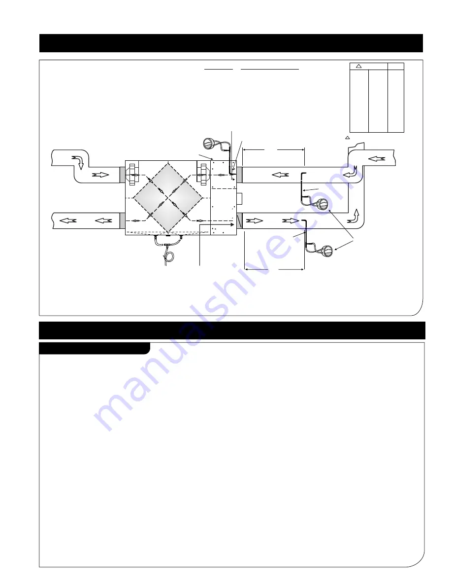
Magnehelic 

gauge

Pitot
tube

Pitot tube

Min 3 ft straight duct

(option #1)

Min 3 ft straight duct

(option #2)

Note: 

To take more accurate readings, use option #1(if possible).

Note:(Option #2)
         

*

For balancing, extension box cover plate is

            provided with 3 holes on supply side and 3 
            holes on exhaust side.
           *Do not use pitot tube to open holes in the 
            insulation as it may block/damage the pitot tube.
           *Take 3 readings on each hole and average 
            all 9 readings for supply and same for exhaust.
           *After finish balancing, plug all six holes with 
            plastic plugs provided with the unit.  

Extension box cover plate

CFM = Opening / Cross-sectional Area(sq.ft.) x velocity(FPM)

Opening area: 0.2196sq.ft.

MAGNEHELIC

0

.1

.2

.3

.4 .5

Opening area: 0.136 sq.ft.

1.  Turn the unit off and disconnect the power supply.

2.  Unlatch the door and lift the door panel towards you, hold it firmly and slide it to the left.

3.  Clean the inside of the 

door

 and 

drain pan

 with a damp cloth to remove dirt and debris 

     that may be present.

4.  Clean the 

filters: 

(twice a year)

          - 

Remove the filters.

          - Vacuum to remove most of the dust.
          - Wash with a mixture of warm water and mild soap. Rinse thoroughly and shake filters 
            to remove water and let dry.

 7.  Check the exterior fresh air supply hood:
          - Make sure there are no leaves, twigs, grass, ice or snow that could be drawn into the vent. 

            Partial blocking of this air vent could cause the unit to malfunction.

 8.  Reassemble the components, Filters and Door (The door is secured when you hear a click.)

 9.  Reconnect the power  and turn on the unit.

5.  Oil/grease defrost damper levers and hinges.

Regular Maintenance

15

Maintenance

  Ø5       Ø6      
0.010   0.004      50
0.012   0.006      60
0.016   0.008      70
0.022   0.010      80
0.027   0.013      90
0.034   0.016    100
0.041   0.020    110
0.048   0.023    120
0.057   0.027    130

P"

CFM

P = Velocity Pressure in inch

"

6.  Check air flow sensors twice a year for lint/dust accumulation. If necessary, clean the sensors 

.


 with a lintfree cloth. Take extra care while handling. make sure supply sensor goes back to


 supply diffuser and exhaust sensor goes back to exhaust diffuser on same original position.

Содержание Deluxe ECM Series

Страница 1: ...1 800 810 3473 Canada 1 800 499 5073 U S A 790 Rowntree Dairy Road Woodbridge ON Canada L4L 5V3 t 905 851 6701 f 905 851 8376 e info reversomatic com www reversomatic com jtantay 1 19 11 Deluxe ECM Series model RHRV D100P ES ECM Polypropylene Core RERV D100 ES ECM Enthalpy Core Superior ECM Series model RHRV S100P ECM Polypropylene Core RERV S100 ECM Enthalpy Core ...

Страница 2: ...al purpose 10 For residential use only The unit must be grounded 11 Do not install in a cooking area 12 This unit is not designed to exhaust combustion and or dilution air for fuel burning appliances CAUTION 1 Turn the unit OFF during construction or repair to avoid filter blockage 2 Exhaust air outside Do not intake exhaust air into spaces within walls crawl spaces garage or into attics 3 Unit has...

Страница 3: ...9 ECM 2 1 3 4 5 6 8 4 7 4 9 4 10 4 11 13 14 25 26 27 28 29 Optional Parts 15 16 17 19 20 21 22 24 23 18 12 Pair Filter 12 x 7 Motor Exhaust Supply ECM 013085 9356ECM Parts List For Deluxe units only For Deluxe auto balance unit only For Deluxe auto balance unit only For Deluxe units only ...

Страница 4: ...0 x 12 MERV 4 9395 2 2 2 4 Temperature Sensor 9326 1 1 1 5 6 ø Polypropylene Backdraft Damper PBD6 2 2 2 6 Blower Supply Exhaust ECM 1 1 1 7 Adjustable Door Latch 9319 1 1 1 8 Drain Spout Assembly 9320 2 2 2 9 Core Locking Bracket 9321 1 1 1 10 Nut 014016 1 1 1 11 Safety Switch 9322 1 1 1 12 Main Control Board ECM 1 1 1 Main Control Board Bracket 9355 2 2 2 13 Door Hinges 9328 1 Set 1 Set 1 Set 14...

Страница 5: ...ty Sensor Defrost Thermistor Relay Output SPDT Max Recommended current 2A Terminal Blocks for HRV ERV External Connections Low Voltage Connection to the Furnace Fan coil or Heat Pump Three wires 5V Power Signal and GND Control Board HRV ERV CHASSIS 120 1 60Hz POWER Exhaust Mounted on HRV ERV Housing RED WHITE RED Note Air Flow Sensors Diffusers and Air Flow Harness are for auto balancing unit only...

Страница 6: ...Board Refer to page 8 to set address A1 A2 A3 Wall Control Unit A1 5V GND SGNL 5V GND SGNL GRN YEL RED 2 GRN YEL RED 3 GRN YEL RED to Control Board to Control Board 1 GRN YEL RED 2 GRN YEL RED 3 GRN YEL RED Wall Control Unit A1 5V GND SGNL 5V GND SGNL 5V GND SGNL Wall Control Unit A1 5V GND SGNL Wall Control Unit A2 5V GND SGNL Wall Control Unit A3 5V GND SGNL 5V GND SGNL 4 GRN YEL RED Wall Contro...

Страница 7: ...t of energizing Y at the thermostat and thereby turning on the cooling system If you identify this type of thermostat you must use the Alternate Interlock Wiring For a furnace connected to a cooling system Wiring Diagram cont d 5 Furnace Fan Coil Heat Pump Interlock Standard Interlock Wiring INTERLOCKING RELAY W R G Y W R G Y C FOUR WIRE TWO WIRE heating only Cooling System FURNACE FAN COIL HEAT P...

Страница 8: ...e when the humidity level becomes lower than the set point The humidity level is measured by an external humidity sensor mounted in the inlet of station 4 The Humidity Mode can be disabled by the user by setting the humidity set point to zero Recirculation Mode When the User requests Recirculation Mode from the Wall Mount Unit the Control will place the supply fan into high speed with damper close...

Страница 9: ...goes to Intermittent Mode and the third LED is on In Intermittent Mode HRV starts with 20 minutes low speed which is followed by 40 minutes off The cycle continues until intermittent mode is exited On a button press it goes into OFF mode and all LEDs are OFF optional Model IC 100 5V Timer Switch Intermittent Switch 7 Timer Switch Intermittent Switch Optional Model TC 100 120P Timer Switch Programm...

Страница 10: ...V ERV runs according to the sequence for Energy Saving mode OFF Press MODE button Mode changed to OFF HRV ERV fans are off no ventilation Note 1 Factory programmed default mode OFF 2 The Mode to be stored in the non volatile memory EEPROM so in case of power outage the system to return in the last selected mode a Functions Adjusting Humidity Setpoint OFF Mode OFF Current Humidity 70 OFF Humidity M...

Страница 11: ...SAVE OFF After pressing the MODE button the unit switches to Normal Mode Airflow setting The current value is n1 which gives you app 63 CFM PROGRAM NORMAL Press button The value is changed to n2 that gives you app 75 CFM PROGRAM NORMAL PROGRAM Press button The value is changed to n4 which gives you app 95 CFM When you select the desired setting for Normal Mode airflow n1 to n4 press MODE button The ...

Страница 12: ...displayed when the unit is in supply fan manual adjustment mode Press or button to increase or decrease supply fan speed SF blinks when the button is depressed It may take several minutes to speed up or slow down Release of or button stops supply fan speed change The changed supply fan speed is stored in non volatile memory which will be used from now on for the current airflow settings N1 N4 and H...

Страница 13: ...quired in the exhaust air duct to prevent outdoor air from entering the unit when the Furnace Air handler is running and the unit is in Standby OFF or in Recirculation Note Typical Installations for House Installation Options for High Rise Condominium Fully Ducted System With Fan Coil System FRESH AIR EXHAUSTED AIR This is a stand alone HRV ERV system which is not connected to a force air system S...

Страница 14: ... 3 are for Aluminum Core RHRV D100AES Map 4 6 are for Polypropylene Plastic Core RHRV D100PES Map 7 9 are for ERV Enthalpy Core RERV D100ES After installation make sure the HRV ERV is properly leveled If not levelled correctly then defrost will not perform effectively and or unit may frost in winter Also make sure you have proper defrost on wall controller according to HRV ERV model no core type N...

Страница 15: ...P trap as shown above T Connector I D Drain Pipe Zip Tie Drain Spout to Drain Drain Pan P Trap Drain Pan For Vertical installation Drain Spout Assembly Rubber washer Drain Spout Nut Steel washer HRV ERV Steel Housing Plastic Drain Pan Minimum 5 Feet 1 Thick Intake Exhaust Insulation CAULKING GRILLE 3 SIDES ONLY NOT ON BOTTOM CAULKING WALLBOX CAULK WALLBOX TO STRUCTURE ON ALL 4 SIDES Distance X Sin...

Страница 16: ...irflow can be determined from the gauge metre reading The value read on the gauge is called the velocity pressure and on the flow meter is called air velocity FPM The Pitot tube comes with a chart that will give the air flow velocity based on the velocity pressure indicated by the gauge This velocity will be in either feet per minute or metres per second To determine the actual airflow the velocity is...

Страница 17: ...sconnect the power supply 2 Unlatch the door and lift the door panel towards you hold it firmly and slide it to the left 3 Clean the inside of the door and drain pan with a damp cloth to remove dirt and debris that may be present 4 Clean the filters twice a year Remove the filters Vacuum to remove most of the dust Wash with a mixture of warm water and mild soap Rinse thoroughly and shake filters to re...

Страница 18: ...nect the fan motor wires remove the screws securing fan assembly pull the fan assembly out of unit check for any accumulation on the blades clean with a small brush if necessary scrub individual fan blades until clean vacuum and wipe put the components back in place reconnect the power supply and turn the unit back on PROBLEMS SOLUTION POSSIBLE CAUSES 1 Air flow is low HRV ERV airflow improperly bal...

Страница 19: ... board refer to problem 4 check all wire connections on timer switch and main control board 6 Defrost Mode does not work fresh air duct maybe frozen HRV ERV airflow improperly balanced for units without built in Automatic Electronic Air balancing defrost damper motor maybe defective Temp sensor maybe defective improper defrost cycle check and remove the ice have professional balancer or contractor ...

Страница 20: ...acific Conditions Rev 3 24th July 2018 U S Department of Energy climate zones map Select HRV ERV For Your Climate Zone 18 Select HRV ERV for your Climate Zone HRVs are recommended for colder climates ERVs are designed for warm humid climates with long cooling seasons ...

Отзывы: