SYSTEM OPERATION
SeaBat 8160
Operator‟s Manual
Page 32
October 6, 2011
Version 5
1.
Off:
No dots are displayed.
2.
Normal:
Only sound
ings with a quality value of “3” are displayed. All dots
are white.
3.
All:
All soundings are white, regardless of their quality or bottom detection
process.
4.
Quality:
Each sounding is displayed based upon the quality value
assigned.
a.
Gray:
Quality 0 (poor colinearity, poor brightness)
b.
Red:
Quality 1 (poor colinearity, good brightness)
c.
Green:
Quality 2 (good colinearity, poor brightness)
d.
Cyan:
Quality 3 (good colinearity, good brightness)
5.
Process:
Each sounding is color-coded based on the weighting used in
the magnitude/phase bottom detection process.
a.
Red:
Magnitude detection
b.
Green:
Phase detection
c.
Cyan:
Blended magnitude/phase detection.
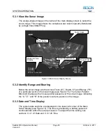
5.6.4 Display or Hide the Sonar Grid (Grid)
The Grid selection allows the operator to control the display of the border and
scale lines that apply to the sonar wedge.
1.
Off
displays only the sonar image.
2.
Border
displays the sonar image with a border around the wedge.
3.
Lines
displays border and depth scale lines.
4.
Full
displays border, depth scale lines, and annotation of the depth scale
in meters.
5.6.5 Freeze the Sonar Image (Freeze)
Selecting “Freeze” prevents the sonar image from being updated while all other
sonar functions continue. This allows prolonged viewing of a particular item when
the display is frozen.
Select “Freeze” again to allow updates to continue.
5.7 Filters Menu
The Filters menu allows the operator to apply range and/or depth filters (depth
gates) to the bottom-detect process to aid in noise reduction and to correct for a
Содержание SeaBat 8160
Страница 103: ...SYSTEM DRAWINGS SeaBat 8160 Operator s Manual Page 93 October 6 2011 Version 5 Figure 31 SeaBat 8160 System Sheet 1...
Страница 104: ...SYSTEM DRAWINGS SeaBat 8160 Operator s Manual Page 94 October 6 2011 Version 5 Figure 32 SeaBat 8160 System Sheet 2...
Страница 105: ...SYSTEM DRAWINGS SeaBat 8160 Operator s Manual Page 95 October 6 2011 Version 5 Figure 33 Array Installation Template...
Страница 107: ...SYSTEM DRAWINGS SeaBat 8160 Operator s Manual Page 97 October 6 2011 Version 5 Figure 35 Array Section 1...
Страница 108: ...SYSTEM DRAWINGS SeaBat 8160 Operator s Manual Page 98 October 6 2011 Version 5 Figure 36 Array Section 2...
Страница 109: ...SYSTEM DRAWINGS SeaBat 8160 Operator s Manual Page 99 October 6 2011 Version 5 Figure 37 Array Section 3...
Страница 110: ...SYSTEM DRAWINGS SeaBat 8160 Operator s Manual Page 100 October 6 2011 Version 5 Figure 38 Four Inch Flange...
Страница 111: ...SYSTEM DRAWINGS SeaBat 8160 Operator s Manual Page 101 October 6 2011 Version 5 Figure 39 Projector...
Страница 112: ...SYSTEM DRAWINGS SeaBat 8160 Operator s Manual Page 102 October 6 2011 Version 5 Figure 40 Hydrophone...
Страница 114: ...SYSTEM DRAWINGS SeaBat 8160 Operator s Manual Page 104 October 6 2011 Version 5 Figure 42 Cable Projector Dry End...

