Resistron RES-430 Скачать руководство пользователя страница 5

Principle of operation

RES-430

5

3

Principle of operation

The resistance of the heatsealing band, which is tem-
perature-sensitive, is monitored 50x per second (60x at
60Hz) by measuring the current and voltage. The tem-
perature calculated with the help of these measure-
ments is displayed and compared with the set point.
The secondary voltage of the impulse transformer is
adjusted by phase-angle control if the measured values
deviate from the set point. The resulting change in the
current through the heatsealing band leads to a change
in the band temperature and thus also its resistance.
This change is measured and evaluated by the
RESISTRON temperature controller.
The control loop is closed: ACTUAL temperature = SET
temperature. Even minute thermal loads on the heatse-
aling band are detected and can be corrected quickly
and precisely.
The thermoelectric control loop which is formed has a
highly dynamic response because purely electrical
variables are measured at a high sampling rate. 

PLEASE NOTE!

RESISTRON temperature controllers play a significant
role in enhancing the performance of modern
machines. However, the full benefit can only be
obtained from the advanced technology offered by this
control system if all the system components, in other
words the heatsealing band, the impulse transformer,
the wiring, the timing signals and the controller itself,
are compatible with one another.

4

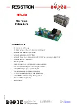
Description of the controller

The microprocessor technology endows the RES-430
RESISTRON temperature controller with previously
unattainable capabilities:

Very simple operation thanks to AUTOCAL, the
automatic zero calibration function.

Good dynamic response of the control system
thanks to AUTOTUNE, which adapts automatically
to the controlled system.

High precision thanks to further improved control
accuracy and linearization of the heatsealing band
characteristic.

High flexibility: Secondary voltage range from 12V
to 42V, current range from 20A to 90A.

Automatic adjustment to the line frequency in the
range from 47Hz to 63Hz.

Increased protection against dangerous conditions,
such as overheating of the heatsealing band.

A time control (timer) function integrated in the con-
troller enables the complete heatsealing process to be
controlled on simple machines, such as table heatse-
aling tools. A configurable relay output can be used to
drive motors, energize magnets etc.

The process data is represented on an LC display with
4 lines and 20 characters. Various display languages
can be selected.
The real heatsealing band temperature is visualized on
the display both as a digital number in °C and in the
form of a dynamic bar.
In addition to the digital and bar indications on the dis-
play, the ACTUAL temperature of the heatsealing band
is supplied to an analog 0…10VDC output. The real
heatsealing band temperature can thus be visualized
on an external temperature meter (e.g. ATR-x).
The RESISTRON temperature controller RES-430 also
features an integrated fault diagnosis function, which
tests both the external system (heatsealing band,
wiring etc.) and the internal electronics and outputs a
selective error message in case of a fault.
The menu in the temperature controller itself can be
used to adapt to different heatsealing band alloys
(Alloy-20, NOREX etc.) and set the required tempera-
ture range (0…300°C, 0…500°C etc.).
The RESISTRON temperature controller RES-430 con-
sists of two components: a motherboard with a power
section for installation in the machine frame and a
separate display terminal. The compact design and the
plug-in connections make this controller easy to install.

We will be pleased to 

contribute our many 

years of experience 

towards optimizing 

your


heatsealing system.

Содержание RES-430

Страница 1: ...omatic optimization AUTOTUNE Automatic phase angle compensation AUTOCOMP as of software revision 100 Automatic frequency adjustment Secondary control Heatsealing band alloy and temperature range selec...

Страница 2: ...interface temperature sensor 23 9 6 Heatsealing band 25 9 7 Startup procedure 26 10 Controller functions 28 10 1 Indicators and controls 28 10 2 Display 28 10 3 Navigation in the menus 30 10 4 Menu st...

Страница 3: ...guarantee trouble free operation of the RESISTRON temperature controller The temperature coefficient must be specified as follows e g Alloy 20 TCR 1100 ppm K NOREX TCR 3500 ppm K The RESISTRON tempera...

Страница 4: ...tall additional components are excluded from the warranty Warranty claims must be examined in the factory and approved by ROPEX 2 Application This RESISTRON temperature controller is an integral part...

Страница 5: ...system High precision thanks to further improved control accuracy and linearization of the heatsealing band characteristic High flexibility Secondary voltage range from 12V to 42V current range from 2...

Страница 6: ...cable Kap 13 How to order auf Seite 50 5 2 1 Scope of supply installation The serial piggyback module is supplied with spacers for installation on the motherboard of the RES 430 Proceed as follows to...

Страница 7: ...UAL temperature closing force You can also export the data as a CSV file for further processing in another PC program In addition the software permits the values in the Con figuration and Settings men...

Страница 8: ...1100ppm Alloy 20 0 300 C Heatsealing band voltage secondary voltage of impulse transformer 12 42VAC Max load current max secondary cur rent of impulse trans former Terminals 5 6 7 8 Two heatsealing ba...

Страница 9: ...Power dissipation max 40W Ambient temperature 5 45 C Degree of protection Motherboard IP00 Display terminal Front IP42 IP65 with transparent front cover Art No 887000 Back IP20 Installation Motherboar...

Страница 10: ...m must be used to fasten the printed circuit board on the underside All national and interna tional regulations must be complied with Connector Piggyback module 6 x fixing hole optional data interface...

Страница 11: ...l cutout RES 430 11 7 2 Display terminal 144 72 Outline dimensions of front frame Panel cutout 138 x 68 0 2 0 2 4 58 9 136 66 144 Front panel Connecting cable length 250mm Rubber seal Mounting clamp C...

Страница 12: ...ite 12 must be heeded additionally Check the tightness of all the system connec tions including the terminals for the impulse transformer windings 6 Make sure that the wiring conforms to the relevant...

Страница 13: ...wiring ROPEX Application Report Do not run the filter supply wires line side parallel to the filter output wires load side RESISTRON temperature controller RES 430 Impulse Transformer Designed accord...

Страница 14: ...rrent cable in order to avoid malfunctions or damage of the controller Step 240 in the Configuration menu must be set to Double for this purpose Band 1 Band 2 Heatsealing band Load cell interface and...

Страница 15: ...temperature sensor IMPORTANT If only ONE heatsealing band is used output terminals 7 8 must be jumped with a high current cable in order to avoid malfunctions or damage of the controller Step 240 in t...

Страница 16: ...on 9 1 View of the controller 9 1 1 Motherboard 9 1 2 Front view of the terminal Connector for terminal Terminals Nameplate Terminals Connector for piggyback module optional data interface Nameplate C...

Страница 17: ...ler settings can be reset to the fac tory settings with step 202 in the Configuration menu Only the language setting step 201 in the Configura tion menu remains unchanged Please refer to section 11 Fa...

Страница 18: ...If time control is on activating the START signal starts the internally parameterized timeout This timeout com prises Starting delay delay at the beginning of the heating phase Heating phase heating...

Страница 19: ...d as the factory setting In this case the heating process begins as soon as the START signal is activated 9 3 3 Setting the heatsealing time The heatsealing time can be set in the range from 0 to 99 9...

Страница 20: ...ling phase of the internal timeout ends when the ACTUAL temperature falls to the specified per centage of the SET temperature This value can be set between 40 and 100 The factory setting is 40 3 Cooli...

Страница 21: ...relay K1 or the sole noid drive closes at the end of the heating phase and opens again at the end of the cooling phase This configuration permits air cooling to be activated with relay K1 or the sole...

Страница 22: ...emperature The dia gnosis ends at the end of the parameterized heatse aling phase As of software revision 008 The temperature diagnosis function can be activated and deactivated with step 217 in the C...

Страница 23: ...uipment temperature or the temperature of the load cell An alarm is output by the controller if the maximum permissible temperature is exceeded The settings for the load cell interface and the tempera...

Страница 24: ...ivated during the closing movement of the sealing jaws for instance 3 End of heating phase A single force diagnosis takes place at the end of the heatsealing phase 4 End of cooling phase A single forc...

Страница 25: ...alibrated for this The first time the heatsealing band is heated to appro ximately 200 250 C the standard alloy undergoes a once only resistance change burn in effect The cold resistance of the heatse...

Страница 26: ...ons are described below 1 Switch off the line voltage and verify that all circuits are deenergized 2 The supply voltage specified on the nameplate of the controller must be identical to the line volta...

Страница 27: ...sfully the main menu appears on the display again Then specify a defined temperature heatse aling temperature with step 101 in the Settings menu and activate the START signal HEAT Alternatively you ca...

Страница 28: ...he display for appro ximately 2 seconds when the controller is switched on This message also includes details of the software ver sion ENTER HAND RESET ROPEX RESISTRON RES 4 MENU key for advancing to...

Страница 29: ...ure on page 32 10 2 4 Error message The fault diagnosis function of the controller is always active If a fault is detected it is indicated on the display immediately in the form of an error message se...

Страница 30: ...here in the menu structure providing a controller alarm is not active In this case the Alarm menu is opened instead If the display is in the home position or an alarm is indi cated and you press the M...

Страница 31: ...pressing the MENU key 2s You can then activate the AUTOCAL function by pressing the ENTER key section 10 8 Automatic zero cali bration AUTOCAL on page 36 If you press the MENU key for longer than 2s...

Страница 32: ...n 213 Lock HAND key 207 Set point reached 205 Temperature range Settings Configuration 1 Force sensor active 2 Force sensor not active 3 Time control OFF 4 Time control ON 5 TCR not variable 6 TCR var...

Страница 33: ...rce tare Configuration 1 Force sensor or force and tem perature sensor active 2 Temp sensor active 3 No sensors active 4 Temp sensor not active 243 Maximum force 1 2 249 Foot switch hold time Continue...

Страница 34: ...page 16 or section 10 4 Menu structure on page 32 Menu Menu step Numbering up to SW revision 006 Numbering as of SW revision 007 Settings menu Heatsealing temperature 1 101 Starting delay 3 103 Heatse...

Страница 35: ...ce it has been entered 10 7 Temperature indication actual value output If the display is in the home position the ACTUAL tem perature is indicated there as a digital value and as a dynamic bar The hea...

Страница 36: ...g the ENTER key The initial temperature ambient temperature of the heatsealing bar s which is currently valid for calibration can be set beforehand in the 0 40 C range using the UP and DOWN keys The z...

Страница 37: ...mong other things this permits the closing movement of the sealing jaws to be started by briefly activating and deactivating the FOOT SWITCH signal The hold time is deactivated if the value entered is...

Страница 38: ...troller you must set Double with step 240 The controller will otherwise be over loaded and damaged beyond repair If you change the configuration with step 240 you must run the AUTOCAL func tion with s...

Страница 39: ...after the AUTOCAL function has been successfully executed section 10 8 Auto matic zero calibration AUTOCAL on page 36 The interval after the end of the AUTOCAL func tion must be less than 2 0s Start A...

Страница 40: ...dication and value selection in Celsius C 2 Fahrenheit Temperature indication and value selection in Fahrenheit F Up to and including software revision 101 only Celsius C can be specified on the contr...

Страница 41: ...nge spe cified in section 6 Technical data on page 8 If a line voltage which is less than the lower limit of the permissible range occurs the controller is switched to a standby mode No more heatseali...

Страница 42: ...switch can then be opened again but the jaws remain closed 3 The heating process must begin immediately wit hout a starting delay 4 The heatsealing time t2 1s must begin when the ACTUAL temperature r...

Страница 43: ...ld be undertaken in the specified order Then ACTUAL temp START signal 180 C t t OFF 0 80 C 1s t Open Relay K1 Closed 95 of 180 C ON FOOT SWITCH OFF ON signal t Step in Configuration menu Setting 210 C...

Страница 44: ...re offered for this purpose in the 0 10VDC range each of which is assigned an error code section 10 21 Error messages on page 44 If a state that requires AUTOCAL occurs or if the con troller configura...

Страница 45: ...ure too high sec 9 4 Frequency fluctuation inadmissible line frequency Heatup time exceeded sec 9 4 1 Force sensor measure range overflow sec 9 5 3 Force sensor measure range underflow sec 9 5 3 Closi...

Страница 46: ...pulse transformer incorrectly sized Temperature too low Temperature too high Calibration failed loose contact ambient temperature fluctuations Data error Current signal incorrect calibration not possi...

Страница 47: ...ult replace controller Partial short circuit delta R Heatsealing band partially bypassed by conducting part clamp opposite heatsealing bar etc Parallel circuit interrupted Wire break heatsealing band...

Страница 48: ...riable temp coeff 1100ppm Step 205 Temperature range 300 C Step 206 Maximum temperature 300 C Step 207 Set point reached 10K Step 208 Set point exceeded 10K Step 210 Cooling mode Absolute Step 211 Sta...

Страница 49: ...is way 3 Restore customer settings Selecting this option restores the customer set tings that were saved as described in 2 When the controller is first delivered the customer settings are identical to...

Страница 50: ...s connector plug in parts and T 430 terminal Line filter LF 06480 Continuous current 6A 480VAC Art No 885500 Impulse transformer See ROPEX Application Report for design and ordering information Option...

Страница 51: ...Fuse 13 H HEAT 27 37 Heatsealing band type 8 Heatsealing time 19 Heatup timeout 23 Hold mode 38 Hold time for FOOT SWITCH signal 37 I Impulse heatsealing method 4 Impulse Transformer 13 Impulse transf...

Страница 52: ...n 35 Temperature range 8 18 Temperature sensor 9 23 Temperature setting 35 Temperature unit 40 Transformer 3 13 50 Type of construction 8 U Undervoltage detection 41 V View 16 Visualization software 7...

Отзывы: