background image

10

Doc No: UMAN\GWY-800-B\0706
REVISION 0

Getting Started

3.1

Introduction To HART

HART® Field Communications Protocol is widely recognized as the industry standard for digitally enhanced 4-20 mA
smart instrument communication. Use of the technology is growing rapidly, and today virtually all major global
instrumentation suppliers offer products with HART communication.

The HART protocol provides a uniquely backward compatible solution for smart instrument communication as both 4-
20 mA analog and digital communication signals are transmitted simultaneously on the same wiring. HART provides
many benefits promised by field bus, while retaining the compatibility and familiarity of existing 4-20 mA systems.

Analog and Digital communication at the same time:

For many years, the field communication standard used by process automation equipment has been a milliampere
(mA) analog current signal. In most applications the milliampere signal varies within a range of 4-20 mA in propor-
tion to the process variable being represented. Virtually all installed plant instrumentation systems use this interna-
tional standard to communicate process variable information.

The HART protocol enables two-way digital communication with smart instruments without disturbing the 4-20 mA
analog signal. Both the 4-20 mA analog and HART digital communication signals can be transmitted simultaneously
over the same wiring. Primary variable and control signal information is carried at the 4-20 mA (if desired), while
additional measurements, process parameters, device configuration, calibration, and diagnostics information is
accessible through the HART protocol over the same wires at the same time. Unlike other “open” digital communication
technologies for process instrumentation, HART is compatible with existing systems.

These enhanced communication characteristics of this technology are reflected in the protocol name, HART which
stands for “Highway Addressable Remote Transducer”.

About HART Technology:

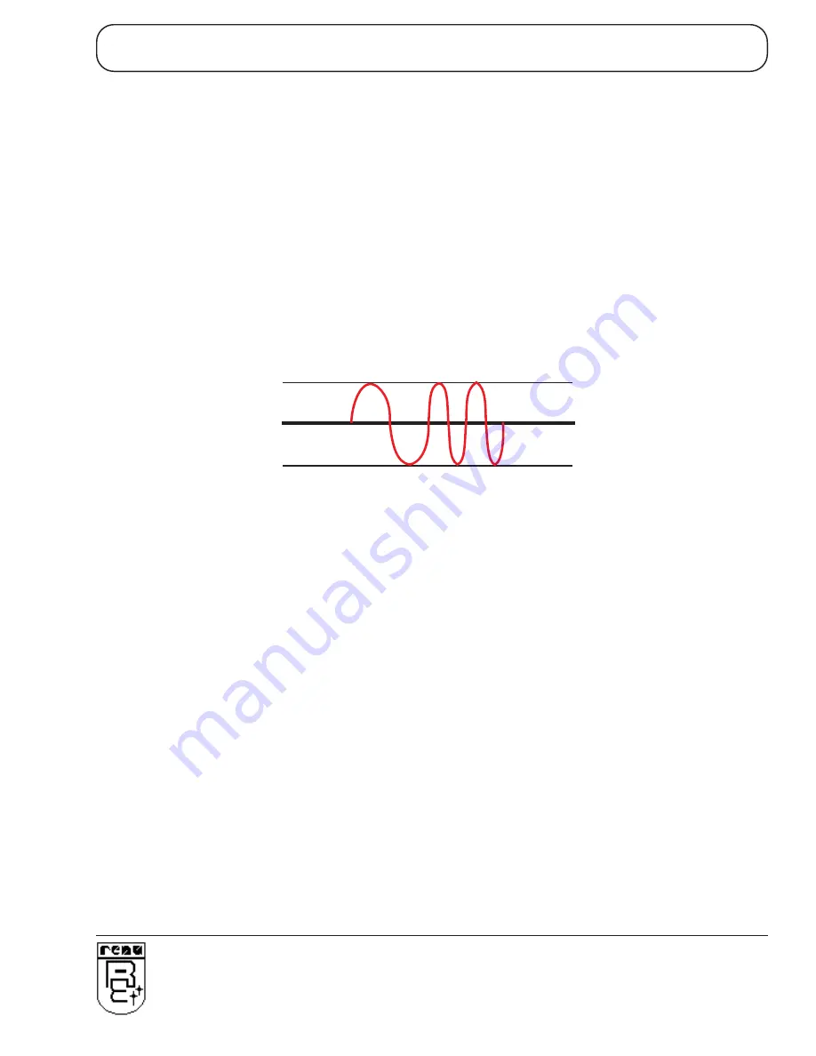
The HART protocol makes use of the Bell 202 Frequency Shift Keying (FSK) standard to superimpose digital
communication signals at a low level on top of the 4-20 mA. Since the digital FSK signal is phase continuous, it does
not interfere with the 4-20 mA signal. A logical “1” is represented by a frequency of 1200 Hz and a logical “0” is
represented by a frequency of 2200 Hz as shown in Figures 1 and 2.

-0.5mA

+0.5mA

Analog Signal

FSK freq:

Logical:

1200 Hz

“1”

2200 Hz

“0”

Simultaneous  Digital Communication

HART uses Frequency Shift Keying to encode digital

information on top of the 4-20 mA analog signal

Содержание GWY-800 Series

Страница 1: ...GWY 800 HART Gateway USER S MANUAL ...

Страница 2: ... customer claims of noncompliance with the product warranty Improper return packaging which makes verification impossible will void the warranty If noncompliance is verified and is not due to customer abuse or the other exceptions described with product warranty Renu Electronics will at its option repair or replace the Product returned to it freight prepaid which fail to comply with the foregoing ...

Страница 3: ...ld be performed on a unit substitution basis only Do not attempt to remove replace or service any printed circuit board components or any hardware software related with display product If problem within the display product occurs contact the factory for service information or repair NOTE Renu Electronics Pvt Ltd is dedicated to providing complete customer service and customer satisfaction If you h...

Страница 4: ...3 4 Configuration of GWY 800 B IBM Download 13 3 4 1 When GWY 800 B can accept configuration 14 GWY 800 B FEATURES 15 4 1 Gateway Modes 16 4 1 1 Master Master Configuration 16 4 1 2 Master Slave Configuration 18 4 2 Repeat Cycle 19 4 3 Control Word 19 4 4 Error Indication Bit 20 4 5 Communication Parameters 20 TYPICAL PROJECTS AND APPLICATIONS 21 5 1 Project Setup 22 5 2 Applications 23 CONFIGURAT...

Страница 5: ...Introduction 1 Doc No UMAN GWY 800 B 0706 REVISION 0 INTRODUCTION In this chapter Purpose of this manual Introduction To Gateway GWY 800 B Specifications ...

Страница 6: ...t be present in all hardwares Renu Electronics Pvt Ltd reserves the right to update information in this publication without prior notice 1 2 Introduction to Gateway Gateway is a Protocol Converter Data sharer for devices like PLCs inverters Adjustable Speed Drives and other Controllers Gateway has two serial ports that connect with two different devices These devices share data through Gateway Gat...

Страница 7: ...ort Operating Temperature 0o to 60o C StorageTemperature 20o to 80o C Humidity 10 to 90 Non condensing Mounting DIN rail or back panel mounting Dimensions DIN rail 105mm L X 40mm D X 51mm W Weight 125 gm approx Certifications CE with UL Immunity to ESD Level 3 as per IEC1000 4 2 Immunity to Transients Level 3 as per IEC1000 4 4 Immunity to Radiated RF Level 3 as per IEC1000 4 3 Immunity to Conduct...

Страница 8: ...Hardware 4 Doc No UMAN GWY 800 B 0706 REVISION 0 HARDWARE In this chapter Dimensional Details and Mounting Instructions Communication Port Details LED Status ...

Страница 9: ... plate also has the provision to screw the unit to the back panel Following drawing shows how to attach the DIN rail plate to the unit Follow instructions given below 1 Attach the DIN rail plate to the unit using the clamps on the DIN rail plate 2 Pull out the clip of the plate 3 Put the unit on the DIN rail 4 Push the clip in to secure the unit on the DIN rail GWY 800 B unit is shipped with a sep...

Страница 10: ...d Pass Through Port is a serial RS232 Port Pinout of these ports are as shown below TX RS422 RS485 DB9 Female 1 5 9 6 5VDC DO NOT USE Signal Ground RX RS422 RS485 RXD RS232C CMOS TXD RS232C TX RS422 RS485 TXD CMOS RX RS422 RS485 6 8 9 7 2 4 5 3 1 PLC1 COM1 Do not use pin no 6 of PLC1 COM1 HART PASS THROUGH CTS DB9 Female 1 5 9 6 DTS Signal Ground DSR RXD TXD RTS 6 8 7 2 4 5 3 2 Pin PBT HART OUT HA...

Страница 11: ...RS422 RS485 Differential Receive also referred as RXB Pin Description for COM 1 PLC 1 User can convert RS485 4 wire Signal Ground system to a 2 Wire Signal Ground system by shorting following signals in the communication cable TX TX A RX B RX SG SG Note If user has attached shield to Earth on Device end leave the shield open on Gateway end If user has connected shield to Signal Ground on Device en...

Страница 12: ...status LED PLC1 Yellow OFF No data receive on PLC port ON Flashing COM1 PLC1 side communication OK OK Green OFF No Firmware Slow Flashing IBM Download Fast Flashing Polling HART Devices ON Device OK PASS Yellow OFF No data received on Pass Through Port THROUGH Flashing Receving data on Pass Through Port Port ...

Страница 13: ...9 Doc No UMAN GWY 800 B 0706 REVISION 0 Getting Started GETTING STARTED In this chapter Introduction To HART Introduction To GWY 800 B GWY 800 B Operation ...

Страница 14: ...way digital communication with smart instruments without disturbing the 4 20 mA analog signal Both the 4 20 mA analog and HART digital communication signals can be transmitted simultaneously over the same wiring Primary variable and control signal information is carried at the 4 20 mA if desired while additional measurements process parameters device configuration calibration and diagnostics infor...

Страница 15: ... variable to be communicated to or from a smart field instrument The HART protocol communicates at 1200 bits per second without interrupting the 4 20 mA signal and allows a host application master to get two or more digital updates per second from a field device 4mA 20mA 1 0 0 1 1 1 0 1 0 Time HART digital communication signal superimposed on the 4 20 mA analog signal Digital Signal Analog Signal ...

Страница 16: ...ecisions based on the parameters values Gateway setup software allows different process parameters to be mapped to any register on the other side PLC Device Microsoft Windows based configuration software Gateway Setup helps user to configure Gateway unit Configuration means making the Gateway unit work as per the system requirements The complete configuration for a unit is termed as Project Projec...

Страница 17: ... device at power on unit will flash the OK LED in fast mode approx 15 seconds So If user want to configure the gateway he she should disconnect the HART device Also after checking the HART device connection it continuously checks the if device is present on the PLC1 COM1 Block execution will be started only after both the devices will be present For Master Slave Mode OK LED is on at power on it ch...

Страница 18: ...RT Port fast OK LED flashing If device is connected it continues normal operation If device is not connected it checks for IBM download mode for 10seconds slow OK LED flashing This sequence continues until either is satisfied If current driver present for PLC1 port is Slave e g Modbus Gateway as Slave First it is checked that whether device is connected on HART Port fast OK LED flashing If device ...

Страница 19: ...GWY 800 B Features 15 Doc No UMAN GWY 800 B 0706 REVISION 0 GWY 800 B FEATURES In this chapter Gateway Modes Repeat Cycle Control Word Error Indication Bits Communication Parameters ...

Страница 20: ...e both Gateway ports are master in nature and devices connected on these ports are slave Gateway ports initiate communication when the proper Gateway Device communication cable is attached Data is transferred in blocks This transfer can either be a continuous process or as per requirement A control word Section 4 3 present in device on either side enabled from Gateway Setup Software can control th...

Страница 21: ... Features 17 Doc No UMAN GWY 800 B 0706 REVISION 0 Let us see the example of Master Master mode as shown in the picture below Configure Gateway ports as PLC1 Protocol Modbus Gateway as Master PLC2 Protocol HART ...

Страница 22: ...ns defining one or multiple registers in the Slave Device correspond ing to one or multiple registers in the Master Device Mapping can be done using the Block definition area so in this mode any Block is used for mapping registers of the two devices NOTES 1 As Gateway Setup Software is common for both the Gateway Modes as a master or slave titles in the Block Definition Area may not be appropriate...

Страница 23: ...ock 4 Cycle 2 Block 1 Cycle 3 Block 1 Block 2 Cycle 4 Block 1 Block 3 Cycle 5 Block 1 Block 2 Block 4 4 3 Control Word Another way of controlling Block execution is by use of the Control Words 16 control words i e 255 control bits are available by which user can control 255 blocks Oth Control bit corresponds Oth bit of control word 1 16st Control bit corresponds 0st bit of control word 2 255th Con...

Страница 24: ...nected to Gateway Using this bit fault at the PLC1 end can be reported to PLC2 Device and fault at PLC2 end can be re ported to PLC1 Device When communication error occurs on PLC1 Gateway sets error bit in PLC2 device Error Indication Bit can only be used in Master Master mode In Master Slave mode any error can easily be detected by a communication time out on the Master Error indication bit can b...

Страница 25: ...Typical Projects 21 Doc No UMAN GWY 300 B 0106 REVISION 0 TYPICAL PROJECTS AND APPLICATIONS In this chapter Project Setup Applications ...

Страница 26: ...at whether device is connected on port2 HART Device If device is connected it checks for the PLC1 If PLC1 is also connected then it continues the normal operation If HART device Note that If PLC1 is not connected then unit does not enter into the IBM mode is not connected it checks for IBM download mode for 10sec This sequence continues until either is satisfied If current driver present for PLC1 ...

Страница 27: ...ct configuration software for HART devices 1 PLC to HART Transmitter Communication 3 HART Transmiteers as a slave on Modbus network 2 Multi dropped HART devices Modbus Protocol 50 RPM x10 0 100 A S T R A Converter Example CNV 02 by Renu Electronics HMI Software ASTRA by Renu Electronics GWY 800 GWY 800 GWY 800 Modbus Protocol PLC X Protocol GWY 800 IBM PC HART Commands PLC1 Modbus Protocol GWY 800...

Страница 28: ...Configuration Software 24 Doc No UMAN GWY 300 B 0106 REVISION 0 CONFIGURATION SOFTWARE In this chapter System Requirements Installation Instruction ...

Страница 29: ...ated and stored in a safe place 1 Launch the Windows operating system 2 Insert the setup CD into CD drive 3 Point to the start button then click RUN 4 In the command line box enter E Disk1 setup exe Click OK This will launch the Gateway installer 5 Follow the instructions to complete setup Gateway Project Each Gateway must be configured before connecting it to the PLC Gateway configuration softwar...

Страница 30: ...Appendix 26 Doc No UMAN GWY 300 B 0106 REVISION 0 APPENDIX In this chapter FlexibleApplications Connection of HART Gateway with the field device ...

Страница 31: ... with the primary master A primary master is typically a DCS PLC or computer based central control or monitoring system A typical installation with two masters is shown in Figure 2 The HART protocol can be used in various modes for communicating information to from smart field instruments and central control or monitoring equipment Digital master slave communication simultaneous with the 4 20 mA a...

Страница 32: ...tructs the slave to do otherwise Data update rates of 3 4 per second are typical with burst mode communication and will vary with the chosen command Burst mode should be used only in single slave device networks 4 The HART protocol also has the capability to connect multiple field devices on the same pair of wires in a multi drop network configuration as shown in Figure 6 In multi drop application...

Страница 33: ... information included in every HART command response provides increased system integrity for critical loops The device status bits in each reply message indicate device malfunctions or other problems such as analog output saturated variable out of limits or communication errors Some HART compatible devices can monitor the device status bits continuously and provide early warning alarms or shutdown...

Страница 34: ...232 RS485 CMOS HART OUT RS232 HART PASS THROUGH Modbus Device Modbus Protocol IBM PC HART s w 24V supply 4 20 mA 250 Pos Neg Loop Powered Transmitter Renu Electronics Pvt Ltd Survey No 2 6 Baner Road Pune 411045 INDIA 24 VDC 10 DC DC EARTH GWY 800 B HART GATEWAY BETA VERSION S N WWYYXXXXX PLC1 OK PASS THROUGH R LISTED 58DN COM1 PLC1 RS232 RS485 CMOS HART OUT RS232 HART PASS THROUGH Modbus Device M...

Страница 35: ... No 2 6 Baner Road Pune 411045 INDIA 24 VDC 10 DC DC EARTH GWY 800 B HART GATEWAY BETA VERSION S N WWYYXXXXX PLC1 OK PASS THROUGH R LISTED 58DN COM1 PLC1 RS232 RS485 CMOS HART OUT RS232 HART PASS THROUGH Modbus Device Modbus Protocol IBM PC HART s w 4 20mA Source 4 20mA Smart Valve ...

Отзывы: