The left part of the display shows the displayed values (volt, ampere, watt, consumed energy) of
a connected unit. The right part of the display shows the selected connection “Radio measuring
display for radio measuring socket” and the current temperature and time.
To activate the 24-hour-temperature monitoring, first push button
“FUNC” repeatedly until the left half of the display shows “Meter” and
“Cancel”. Then push the button “-/OFF”, until the display shows “Manu”.
The radio measuring display/thermostat will now monitor the set tem-
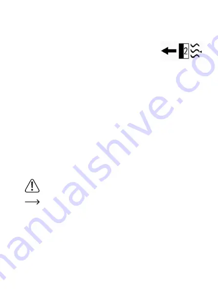
perature. If, for example, the radio measuring switching socket 2 was
activated, the symbol will appear as shown in Figure 9.
Example:
You have chosen the operating mode “Cooling” and temperature 22 °C. An air conditioning unit
is connected to the selected switching socket. If the temperature in the room in which the radio
measuring display/thermostat is located rises above the set “target temperature” of 22 °C for a
certain time, the radio measuring display/thermostat will send the signal “activate” to the chosen
radio switching socket.
The air conditioning unit will start to work. The left half of the display will now alternate between
the mains voltage in Volt (V) and the current required by the connected device in Ampere (A).
Additionally, the power of the connected device in Watt (W) is displayed below this. The very
bottom of the display shows the total of power used in kW/h.
If the room temperature permanently drops below the “target temperature” (here: 22 °C), the air
conditioning unit is switched off again by the radio measuring display/thermostat. To deactivate
this 24-hour temperature monitoring, push the button “-/OFF” repeatedly until “Cancel” appears
in the display.
If 24-hour temperature monitoring is deactivated again (Cancel), the switching condi-
tion that was activate at deactivation will be preserved. Therefore, you must switch off
any activated switching sockets manually after deactivation (see chapter 9).
The temperature-controlled activation and deactivation of the switching sockets, as
well as updating of the measured values, always happens with a delay.
If several switching sockets are to be controlled by the radio measuring display/ther-
mostat, each switching socket generally can be programmed individually with “Heat-
ing” or “Cooling”. Since, however, only one room (where the measuring display/ther-
mostat is located) will be used for temperature monitoring, we recommend “concurrent
programming” (all heating or all cooling).
Figure 9
30


