


VIONiC REXM20/REXT20 installation guide
6
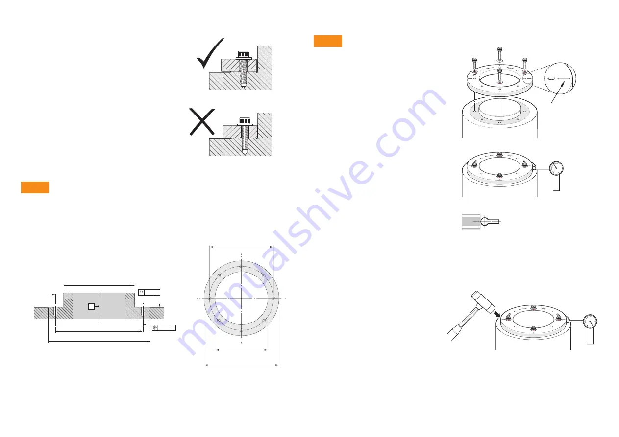
REXM20/REXT20 installation
REXM20/REXT20 should be flange mounted onto a
flat surface; this eliminates all installation errors except
eccentricity, which can be compensated using twin
readheads.
X
Although taper mounting is best for thin
cross-section rings, it is not suitable for thick
cross-section REXM20/REXT20 rings.
X
The REXM20/REXT20
ring should be flange
mounted onto a flat surface to minimise
2-per-rev distortion.
X
Some eccentricity of the ring is acceptable
because it will be compensated by the use
of twin readheads.
X
To avoid distorting to the scale, the
REXM20/REXT20
should not be interference fitted.
There is a mounting face on the lower side of the
REXM20/REXT20 ring. A flat surface should be
prepared on the mounting shaft to match. The total axial
run-out of the mounting surface should be within 10 µm.
For dimensions D1, D2, D3, D4 and number of holes N, refer to
.
N × M5
× 10 deep
(< D1 ‑0.75)
D4
A
D1
D4
D2
D3
0.01
Ø 0.2
A
A
X
Remove the protective film from the surface
of the REXM20/REXT20 ring.
X
Clean the mounting face on the lower side
of the REXM20/REXT20. Clean the mating
surface on the mounting shaft.
X
Place the REXM20/REXT20 ring onto the
mounting shaft, then insert four M5 screws
with flat washers into the four screw holes by
the fiducial marks.
CAUTION:
Do not tighten the screws at this
point – simply engage the threads, ensuring
that the heads do not touch the ring.
NOTE:
For partial arc applications refer to
orientation for partial arc applications’, page 8
X
Set up a Dial Test Indicator (DTI) to measure
the run-out on the REXM20/REXT20 ring.
NOTE:
At this stage the ring is not firmly
fixed, so to avoid causing the ring to shift
position, rotate the ring slowly
and smoothly.
X
Where the DTI shows the lowest radius
reading, gently tap the opposite side of the
ring on the edge using a rubber mallet until
the DTI reading is approximately at the ‘mid
point’ of the run-out.
X
Now find the new lowest radius reading and
again tap the opposite side of the ring with a
rubber mallet until the DTI reading is at the
‘mid point’ of the run-out.
X
Continue this process until the run-out of the
ring is approximately 30 µm (0.0012 inches).
Use a DTI with low exertion force
to avoid scratching the scale
surface. A DTI with a ruby ball
stylus is recommended as a further
precaution against scratches.
Dimple or slot
indicates
fiducial mark
Step 1
Shaft preparation
Mounting
Step 2