*Notice: The information in this document is subject to change without notice
Tsi301
Notes
Tsi301 HyperTransport to PCI User Manual
5-36
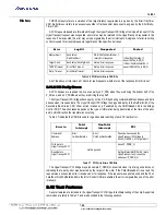
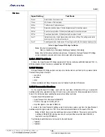
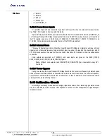
Table 5.2 summarizes the addresses and Vector bit values for the 16 interrupt controller registers.
Serial ROM (SROM) Interface 1 Rx
90h
Serial ROM (SROM) Interface 1 Tx
94h
Serial ROM (SROM) Interface Control
98h
Reserved
9Ch
Block 0, Interrupt 1
Block 0, Interrupt 0
A0h
Block 0, Interrupt 3
Block 0, Interrupt 2
A4h
Block 1, Interrupt 1
Block 1, Interrupt 0
A8h
Block 1, Interrupt 3
Block 1, Interrupt 2
ACh
Block 2, Interrupt 1
Block 2, Interrupt 0
B0h
Block 2, Interrupt 3
Block 2, Interrupt 2
B4h
Block 3, Interrupt 1
Block 3, Interrupt 0
B8h
Block 3, Interrupt 3
Block 3, Interrupt 2
BCh
Interrupt Block Level 0
Interrupt Diagnostics
Special Interrupts
C0h
Interrupt Special Block
Interrupt Block Level 3
Interrupt Block Level 2
Interrupt Block Level 1
C4h
Reserved
Transmit Buffer Counter Maximum 0
C8h
Reserved
Transmit Buffer Counter Maximum 1
CCh
Reserved
D0h
Debug
D4h
Reserved Space
HyperTransport Diagnostics
D8h
Diagnostics Link 0 Receive CRC Expected
DCh
ECh - EFh are Reserved
Diagnostics Link 0 Receive CRC Received
F0h
Diagnostics Link 1 Receive CRC Expected
F4h
Diagnostics Link 1 Receive CRC Received
F8h
Scratch
FCh
Interrupt Register
Address
Vector [1:0] Bit
Default Value
Block 0, Interrupt 0
A1h–A0h
00b
Block 0, Interrupt 1
A3h–A2h
01b
Block 0, Interrupt 2
A5h–A4h
10b
Block 0, Interrupt 3
A7h–A6h
11b
Block 1, Interrupt 0
A9h–A8h
00b
BBlock 1, Interrupt 1
ABh–AAh
01b
Block 1, Interrupt 2
ADh–ACh
10b
Block 1, Interrupt 3
AFh–AEh
11b
Table 5.2 Interrupt Controller Addresses and Vectors
Figure 5.1 CSR Function 0 Space Map


