


RH850/U2A 292pin
9. Precautions
R20UT4970ED0101 Rev.1.01
Page 55 of 67
July 08, 2022
9. Precautions
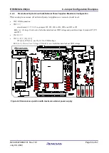
9.1
Power-Off Sequence
A dedicated sequence needs to be applied, when the power supply to the board is turned off.
Please follow the below sequence:
1.
At first turn the RESET switch SW1 into '2-3 ON' position, so that RESET is permanently asserted.
Alternatively keep SW1 manually in' 2-1 (ON)' position.
1.
Turn off the board power supply.
2.
After the power supply has shut down, release RESET by returning SW1 into the 'OFF' position.
For details how to apply a RESET, please refer to section
9.2
CAN0RX is Shared with FLASH Programmer Signal FLMD1
When using this product plugged into a motherboard where CAN0 is connected to the CAN-
transceiver the FLASH programmer will not work.
This is because the CAN0RX function is shared with the FLMD1 function on the same device
PIN.
Most CAN-transceiver are driving the RX line actively and the FLASH programmer then is
not able to change signal level as required for flashing.
9.3
DeepSTOP Mode when using SVR
It is not possible to use the SVR function (JP23[2-3]: VDD = 1.09 V (SVR_OUTPUT)) together
with DeepSTOP mode operation.
If DeepSTOP mode operation is needed, please use JP23[1-2]: VDD = 1.12 V (VDDs) for core
voltage.
Please refer to
3.3 Device Core Voltage (VDD) Selection
for further details about VDD voltage
setting.
Содержание RH850 Series
Страница 67: ...Back Cover RH850 U2A 292pin R20UT4970ED0101 ...