


N1-HV/AC Series
User Manual
13
N1-HV/AC Series
User Manual
12
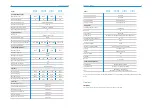
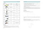
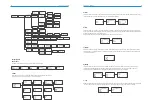
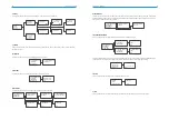
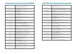
Object
Quantity
Description
A
B
C
D
E
F
G
H
I
J
K
L
M
N
O
P
1
1
2
4
4
1
1
1
1
3
1
1
4
1
1
1
N1-HV/AC series inverter
Bracket
Battery Connectors (1* positive, 1*negative)
PV Connectors (2* positive, 2*negative)
PV Pin contact (2* positive, 2* negative)
AC Terminal
EPS Terminal
8P Pluggable Terminal Block
WiFi or GPRS Module(Optional)
Ethernet RJ45 Connector
M5 Screw
Earth Terminal
Expansion tubes& Expansion screws
Meter
User Manual & Quick installation guide
Quality Certificate
Open the package and pick the product, check that if there is any distortion or impaired during the transportation. Meanwhile,
check that if the relating accessories and the materials are here, you can see the accessories list in the table.
The instruction manual is an integral part of the unit and should therefore be read and kept carefully.
It is recommended that the packaging should not be removed until the unit is located in the installation site.
5.2 Check for transport damage
Check if the N1-HV/AC series inverter has some visible external damage, such as cracks in the housing or display please
contact with your dealer if you find any damage.
5.3 Installation precaution
The N1-HV/AC series inverter is designed for outdoor installation (IP65)
Make sure the installation site does not fall into one of the following conditions:·Do not install the inverter in direct sunlight.
·
Do not install the inverter on flammable construction material.
·
Do not install the inverter in areas where highly flammable materials are stored.
·
Do not install the inverter in potentially explosive areas.
·
Do not install the inverter during periods of precipitation or high humidity (>95%); Moisture trapped within the location
may cause corrosion and damage to the electric components.
·
Provide adequate ventilation when using batteries, and also read the warning label on the bottom of the inverter.
·
Install the inverter in a location that maintains an ambient air temperature that is less than 40°C;That is to maintain a safe
internal component temperature; the inverter would reduce power if the ambient air temperature exceeds 40°C. • The
inverter should be installed in a location that is not accessible for children.
·
The inverter emits a slight vibrating noise when operating, which is normal and no effect on performance.
·
The slope of the wall should be within ±5°.
·
The inverter is heavy, ensure the mounting place is strong enough to hold the weight of the inverter.
·
If you install the inverter in a cabinet, closet or other small enclosed area, sufficient air circulation must be provided in
order to dissipate the heat generated by the unit.
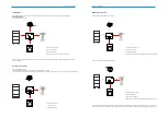
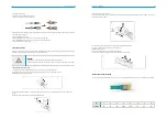
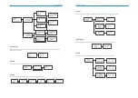
Figure 5-1 inverter space size
5.4 Available space
500mm
500mm
300mm
300mm
300mm
A
B
C
D
E
F
G
H
I
J
K
L
M
N
O
P


