


11
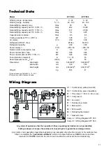
Wiring Diagram
H1 = Control lamp, yellow (tank full)
H2 = Control lamp, green (operation)
K1 = Time relay (t = 30 min / Pos. max.)
M1 = Compressor
M2 = Fan motor
P1 = Running hour meter
S1 = Main switch
S2 = Micro switch
S3 = Defrosting thermostat
Y1 = Solenoid valve
Comp. A = Wiring Diagram ETF 300
Comp. B = Wiring Diagram ETF 550
Technical Data
Model
ETF 550
Working range - temperature
°C
3 - 32
Working range - humidity
% r. h.
40 - 100
Dehumidifying capacity, max.
l/day
55
Dehumidifying capacity at 30°C / 80% r. h.
l/day
50,08
Dehumidifying capacity at 20°C / 70% r. h.
l/day
28,59
Dehumidifying capacity at 10°C / 60% r. h.
l/day
6,95
Capacity water container
litres
6,5
Cooling capacity at 5°C t
v
/ 45°C t
k
kW
2,1
Air volume
m³/h
600
Refrigerant (FCKW –free)
R 407 C
Refrigerant quantity
g
260
Power supply 1~
V / Hz
~230 / 50
Rated current consumption, max.
A
3,8
Power consumption, max.
kW
0,82
Power consumption at 20°C / 70% r. h.
kW
0,60
Fuse protection (required)
A
16
Sound pressure level L
pA
1m
1)
dB (A)
59
Dimensions total depth
mm
590 (480)
2)
total width
mm
555
total height
mm
900 (710)
2)
Weight
kg
41
ETF 300
3 - 32
40 - 100
30
26,2
13,7
5,4
6,5
1,29
350
R134a
260
~230 / 50
3,3
0,65
0,45
10 - 16
48
590 (465)
2)
540
900 (620)
2)
35,5
1) Noise measuring DIN 45635 - 13 - KL 3
2) Dimensions without transport handle
Any mode of operation other than specified in these operating instructions is not permissible!
Failing to observe it causes the customer to lose all rights to guarantee or damage claims.
Any claims under guarantee regarding materials can be accepted only when the orderer or his customer has
filled in completely the
“guarantee certificate”
which is enclosed with every REMKO-device and has
returned it to REMKO GmbH & Co. KG in due time after the unit’s sale and commissioning.
Comp. A
Comp. B
Содержание ETF 300
Страница 2: ......