


7
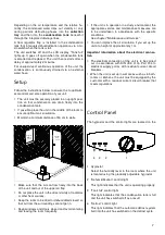
Control Panel
The hygrostat and the control lights are located on the
1 Hygrostat
Select the humidity level in the room where the unit
is located using the gradually adjustable hygrostat.
2 “Dehumidification“ control light
This light indicates that the unit is operating properly.
3 “Tank full“ control light
This light indicates that the condensation tank is full
and the unit has switched off as a result.
4 “Defrost“ control light
This light indicates that the automatic defrost system
built into the unit has switched on the defrost cycle.
1
4
3
2
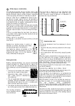
Depending on the air temperature and the relative hu-
midity, the condensed water drips out steadily or only
during periodic defrosting phases into the
collection
tray
and then into the
condensation tank
beneath it
through the integrated drainage lines.
A float regulator flap is installed in the condensation
tank that interrupts dehumidification operation via a mi-
croswitch when the tank is full.
The unit switches off and the LCD display "Tank full“
lights up. It goes off again when the condensation tank
is emptied and replaced. The unit then restarts after a
delay of approximately 2 minutes.
For unsupervised, continuous operation of the unit, the
condensation is continuously drained via an external
water hose.
Setup
Follow the instructions below to ensure the to optimum,
economical and safe operation of your unit.
◊
The unit must be securely placed in an upright posi-
tion so that condensation can drain freely into the
condensation tank.
◊
If possible, place the unit in the middle of the room to
ensure optimum air circulation.
◊
Maintain a minimum distance of 50 cm to walls.
◊
Make sure that the air can flow freely into the back
of the unit and out of the upper air flap.
◊
Do not place the unit in the direct vicinity of radiators
or other heat sources.
◊
Keep the room to be dried or dehumidified closed so
that air from the surroundings cannot get in.
◊
Keep windows and doors closed and avoid entering
and leaving the room frequently.
◊
If the unit is in operation in a dusty environment, the
appropriate service and maintenance measures are
to be undertaken in accordance with the specific
conditions.
See chapter "Maintenance and Service".
◊
You can improve the air circulation if you set up the
unit at a height of approximately 1 m.
Important information about the electrical connec-
tion
◊
The electrical connection of the unit is to be carried
out in accordance with DIN VDE 0100, Part 704 to
electrical supply points with residual current circuit
breakers.
◊
When the unit is set up in wet areas such as in bath-
rooms
or kitchens, the unit must be equipped by the
customer with a residual current circuit breaker that
meets regulations.
Fenster
geschlossen
halten
Tür
geschlossen
halten
Wan
dabs
tand
min
d. 0,5
m
Ab
sta
nd
zu
H
eiz
kö
rpe
rn
od
er
an
de
ren
W
ärm
eq
ue
lle
n h
alt
en
keep the
window
closed
keep the
door
closed
minim
um d
istan
ce of
0,5 m
Ple
as
e k
ee
p d
ista
nc
e t
o t
he
rad
iat
or
or
oth
er
he
ati
ng
so
urc
es
Содержание ETF 240
Страница 1: ...REMKO ETF 240 Portable Air Dehumidifier Edition GB S10 Operation Technology REMKO powerful like a bear...
Страница 2: ......
Страница 15: ......