


4 | U1500E-11 Gas Fireplace
U1500E-11 Gas Fireplace
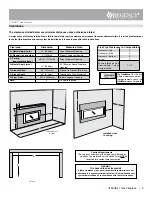
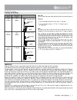
Mantel Clearances
Due to the extreme heat this fireplace emits, the mantel clearances
are critical. Combustible mantel clearances from top of front facing
are shown in the diagram on the right.
Note: Ensure the paint that is used on the mantel and the
facing is "high quality" or the paint may discolour.
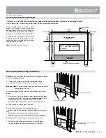
Mantel Leg Clearances
Combustible mantel leg clearances as per diagram:
Wood Studs
0
Non-combustible
Facing
34"
(864mm)
24-1/4"
(616mm)
10"
(254mm)
30"
(762mm)
Top of
Fireplace
Opening
20"
(508mm)
6"
(152mm)
12"
(305mm)
29-1/2"
(749mm)
Steel
Stud
(On Edge)
1"
(25mm)
23-7/8"
(606mm)
6" (152mm)
12" (305mm)
Drywall
From base
of unit
25"
(635mm)
4"
Allowable mantel
leg projection
7-1/8” (181mm)
10”(203mm)
13”( 279mm)
1.5" (38mm)
MANTEL LEG
3-1/4" (83mm)
Non-Combustible
7”
(178mm)
(102mm)


