Regency GFI300L Gas Fireplace Inbuilt
19
INSTALLATION
919-332a
05/08/14
2
GFI300L
5
1
2
4
3
3
2
3
4
2
5 mm
6
1
4
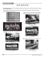
In position, the bark pattern on Log 3 should line up with the pattern on
Log 2. It should appear as if one log has split during burning.
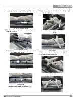
4. Place Log 4 on the burner, rest the back of Log 4 on the tab located on
the left side of the burner.
IMPORTANT: A 5 mm gap must be maintained between Logs 3 and 4 to
ensure proper burner function.
5. Place Log 5 across Logs 1 and 2. The left side of the "Y" in Log 5 fi ts into
the notch in Log 1. The other end of the Log 5 will rest on the burner tray,
covering the hole as shown below.
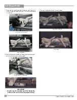
6. Place Log 6 across Logs 1 and 4. The top part of Log 6 fi ts into the
notch on the left hand side of Log 1. The bottom end of Log 6 should
sit so it covers a screw on the burner tray.
Log 6 fi ts in notch on Log 1
Log 7 in position
Logs 2 & 3 - continuous bark line
Log 4 rests against tab on burner
5 mm gap between Logs 3 & 4
Log 5 covers hole on burner
tray trim
3
4
5 mm
I
MPORTANT
Maintain a 5mm gap between Logs 3 & 4

