background image

16

Regency FG38 FireGenie Freestanding Gas Stove

OPERATING INSTRUCTIONS

COPY OF THE LIGHTING PLATE INSTRUCTIONS 

WARNING: 

DO NOT SPRAY AEROSOLS IN THE VICINITY OF 

THIS APPLIANCE WHILE IN OPERATION.

FOR YOUR SAFETY READ BEFORE LIGHTING

A) BEFORE LIGHTING smell all around the appliance area 

for gas. Be sure to smell next to the floor because some 

gas is heavier than air and will settle on the floor.

    WHAT TO DO IF YOU SMELL GAS

  -  Do not try to light any appliance

  -  Do not touch any electric switch, do not use any  

  phone in your building

  -  Immediately call your gas supplier from a neighbors  

  phone. Follow the gas supplier’s instructions.

  -  If you cannot reach your gas supplier, call the  

  fire department.

918-247c

WARNING: If you do not follow these instructions exactly, a fire or explosion may result 

causing property damage, personal injury or loss of life. Improper installation, adjustment, 

alteration, service or maintenance can cause injury or property damage. Refer to the owner’s 

information manual provided with this appliance. For assistance or additional information 

consult a qualified installer, service agency or gas supplier.

B) Do not use this appliance if any part has been under water. 

Immediately call a qualified service technician to inspect 

the appliance and to replace any part of the control system 

and any gas control which has been under water.

This appliance needs fresh air for safe operation and 

must  be  installed  so  there  are  provisions  for  adequate 

combustion and ventilation air.

 LIGHTING INSTRUCTIONS

TO TURN OFF GAS APPLIANCE

This appliance must be installed in accordance with local codes, if any; if not, 

follow the current CAN1-B149/ANSI Z 223.1 AS / NZS 5601

DO NOT REMOVE THIS INSTRUCTION PLATE

Part #: 918-247b (for FG38 & IG35 only)

Colours:  

Black on Grey, except for parts in RED

Size:   

100%

Feb. 9/06: no changes artwork.

Dec. 18/18: Rev.C updated st added wording

1)  Press the ON/OFF switch once.

2)  The LED will flash.

CAUTION: Hot while in operation. Do not touch. Severe Burns may result. Due to high surface 

temperatures keep children, clothing and furniture, gasoline and other liquids having flammable 

vapors  away.  Keep  burner  and  control  compartment  clean.  See  installation  and  operating 

instructions accompanying appliance.

STOP! Read the safety information above on this label.

1)  Plug the power cord into a power outlet.

2)  Press and release the ON/OFF switch once to start 

the unit. The LED will be lit.

3)  After approximately 8 seconds the spark ignition 

system will spark for 8 seconds to light the main 

burner.

4)  If the main burner does not light, repeat step 2 to 

restart.

3)  Turn off all electric power to the unit if service is 

to be performed.

You may shut off the pilot during prolonged non use periods to conserve fuel.

SUITABLE ONLY FOR INDOOR INSTALLATION

Содержание FG38LPG2-BRA

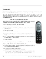
Страница 1: ...rized installer service agency or the gas supplier FOR YOUR SAFETY Do not store or use gasoline or other flam mable vapours and liquids in the vicinity of this or any other appliance Installation and service must be performed by an authorized installer service agency or the gas supplier PLEASE KEEP THESE INSTRUCTIONS FOR FUTURE REFERENCE Owners Installation Manual 919 985b Models FG38NG2 BRA FG38L...

Страница 2: ...approx 30 seconds turn the on again check all the functions work fan speed can be adjusted flame height can be adjusted etc Note To view a step by step pairing video please visit regency fire com au Customer Care Fireplace Care Videos Note The Remote Control Handset has a set of unique ID codes that is pre programmed into its memory This set of ID codes helps to differen tiate one Remote Control H...

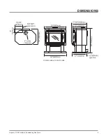
Страница 3: ...Regency FG38 FireGenie Freestanding Gas Stove 3 FG38NG2 BRA FG38LPG2 BRA DIMENSIONS ...

Страница 4: ...0 Log Installation 10 Front Door Installation 12 Test for Flue Spillage 12 Remote Control optional 13 Final Check 13 Wiring Diagram 13 Operating Instructions First Fire 14 Operating Instructions 14 Lighting Instructions 14 Shutdown Instructions 14 Fan Operation 14 Adjusting Flame Height 15 Summary of Controls 15 Normal Operating Sounds of Gas Appliances 15 Copy of Lighting Plate Instructions 16 Ma...

Страница 5: ...ncy Gas Fireplace 2 87mm 1 61mm 257 Distributed by Western Australia Air Group Australia 28 Division St Welshpool WA 6106 Eastern Australia Fireplace Products Australia Pty Ltd 1 Conquest Way Hallam VIC 3803 To be installed by an authorised person in accordance with installation instructions provided with the appliance Part 919 988 Colour Black on Grey Size 100 Dec 6 18 Created decal 4 34 w x 1 56...

Страница 6: ...VELINTFROMCARPETING ETC IT IS IMPERATIVE THAT CONTROL COM PARTMENT BURNERSANDCIRCULATING AIR PASSAGEWAYS OF THE APPLIANCE BE KEPT CLEAN DUE TO HIGH TEMPERA TURES THE APPLIANCE SHOULD BE LOCATED OUT OF TRAFFIC AND AWAY FROM FURNITURE AND DRAPERIES THISAPPLIANCECANONLY BEFLUEDINACCORDANCE WITH AS NZ5601ORLOCAL CODES FAILURE TO INSTALL THIS APPLIANCE CORRECTLY MAY CAUSE A SERIOUS HOUSE FIRE Provide a...

Страница 7: ...ic pressure zone as the combustion air inlet to the burner This heater must be properly connected to a flueing system WARNING Operationofthisheaterwhennot connected to a properly installed and main tained flueing system can result in carbon monoxide CO poisoningandpossibledeath FLUEING This heater is a flued appliance and must be connected to a chimney flue in accordance with the installation code...

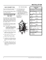
Страница 8: ...utlet 8 5 The pressure check should be carried out with the unit burning and the setting should be within the limits specified on the safety label 6 When finished reading manometer turn off the gas valve disconnect the hose and tighten the screw clockwise with a 1 8 flat screwdriver Screw should be snug but do not over tighten S I T Valve Description 1 On Off Solenoid Valve EV1 2 On Off Solenoid V...

Страница 9: ...ve the control box cover by undoing the 3 screws Maneuver through antenna Jumper Location Jumper 15 Adjusting the Outlet Pressure All the adjustments must be carried out in the following order Remove the modulator plastic cap A using needle nose pliers Maximum pressure Turn the unit ON to its highest input rating Screw in the nut B to increase the outlet pressure and screw it out to decrease it Us...

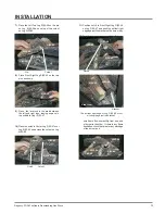
Страница 10: ...ation The gas log kit contains the following a 02 65 Rear Log b 02 56 Middle Left Log c 02 44 Front Left Log d 02 46 Left Top Log e 02 45 Front Right Log f 02 47 Center Log g 02 48 Middle Right Log h Embers i Lava Note Install Optional Brick Panels prior to installing logs Embers Embers The 02 refer numbers i e 02 65 are molded into the rear of each log 1 Carefully remove the logs from the box and...

Страница 11: ...nd of burner to the other If there is any flame hesitation check that area for any blockage of the burner port F 0 2 4 7 E 02 45 A 02 65 G 02 48 D 0 2 4 6 B 02 56 C 02 44 Cutout Pin D 02 46 B 02 56 A 02 65 7 Place the Left Top Log D 02 46 on the pin on Log B 02 56 and on top of the cutout on Log A 02 65 E 02 45 C 02 44 8 Place Front Right Log E 02 45 on the two pins as shown 9 Place the lava rock ...

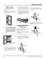
Страница 12: ...nsmaking sure the two pieces are flush together See diagram 1 3 Close the door The latch plate must be centered around the alignment pin See diagram 2 If the latch plate interferes with the corner of the stove you may want to angle the plate slightly so the door closes easier Diagram 2 Diagram 3 4 The latches should already be at the proper setting If they are too hard or too easy to close you may...

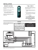
Страница 13: ...a convenient location to mount the hand held transmitter protection from extreme heat is very important By using the wall mounting plate to house the transmitter the remote can also be used as a wall thermostat FINAL CHECK Before leaving this unit with the customer the installer must ensure that the appliance is firing correctly This includes 1 Clocking the appliance to ensure the cor rect firing ...

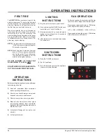
Страница 14: ... is to be performed FIRST FIRE The FIRST FIRE in your heater is part of the paint curing process To ensure that the paint is properly cured it is recommended that you burn your fireplace for at least four 4 hours the first time you use it with the fan on When first operated the unit will release an odour caused by the curing of the paint and the burning off of any oils remaining from manufacturing...

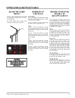
Страница 15: ...operation of a gas regulator or valve Unit Body Firebox Different types and thicknesses of steel will expand and contract at different rates resulting in some cracking and ticking sounds will be heard throughout the cycling process OPERATING INSTRUCTIONS WARNING DO NOT SPRAY AEROSOLS IN THE VICINITY OF THIS APPLIANCE WHILE IN OPERATION ADJUSTING FLAME HEIGHT Therearesixflamesettingsthatcanbeadjust...

Страница 16: ...trolsystem and any gas control which has been under water This appliance needs fresh air for safe operation and must be installed so there are provisions for adequate combustion and ventilation air LIGHTING INSTRUCTIONS TO TURN OFF GAS APPLIANCE This appliance must be installed in accordance with local codes if any if not follow the current CAN1 B149 ANSI Z 223 1 AS NZS 5601 DO NOT REMOVE THIS INS...

Страница 17: ... the flameoftheburnerperiodically makingsure the flames are steady not lifting or floating If there is a problem call an authorized service person 4 The appliance and flueing system must be inspected before use and at least annu ally by an authorized field service person to ensure that the flow of combustion and ventilation air is not obstructed During the annual service call the burners should be...

Страница 18: ...put in place 4 Install side retainers 5 Install door catch plate 6 Install the 24 nuts loosely do not tighten yet 7 Tighten side panels nuts using the following procedure a tightentop bottomoutsidecornernuts 2 b tighten inside nuts 3 c tighten top bottom inside corners 2 8 Tighten the 10 nuts on center glass retainer 9 Repeat step 7 for other side panel 10 Replace new gasket by gluing it in place ...

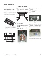
Страница 19: ...soft cloth on thebaseoftheunitsothatwhenthepedestal doorisopenitdoesn tscratchthepaint See diagram below 5 Open the side pedestal door by unscrewing the 2 Philips screws 6 Disconnect the valve wires from the 9 pin connector located on the right side of the connector Valve wires consist of 2 orange 1 yellow and 2 purple colored wires MAINTENANCE 7 At this point you should disconnect the gas at the ...

Страница 20: ...N A N A N A N A 910 089 Flame Cable N A N A N A N A N A N A N A N A 910 088 Spark Cable N A N A N A N A N A N A N A N A 910 084 Control Box N A N A N A 911 101 Control Box N A N A N A N A N A N A 910 527 Manual Control Switch N A N A N A N A N A N A 910 080 Valve 910 521 Control Box Cable 1 910 522 Control Box Cable 2 910 523 Control Box Cable 3 910 525 Control Box Cable 4 N A 2 1 1 3 N A 2 N A N ...

Страница 21: ...Pedestal Back 19 756 518 Side Panel Door Assy Right Side 20 756 520 Side Panel Door Assy Left Side 21 560 031 Hinge for Side Panel Part Description Part Description 23 904 258 Side Panel Door Magnet 24 948 255 Door Latch c w Hook 25 750 095 Door Hold Down Bracket 30 750 026 Rear Panel 32 730 028 Firebox Baffle 33 560 535 False Top Assembly 34 590 273 Flue Attachment Bracket 35 590 930 Ult 6 Flue C...

Страница 22: ... Orifice LPG at 31 MJ h 71 752 528 Rear Log Bracket Assy 72 910 082 Ignition Direct Spark Assy NG LPG 75 732 930 Log Set 78 752 525 Burner Assy NG LPG 910 083 Module Sit 230V 910 084 Control Box ECS 910 088 Wire ECS Module Spark Red 910 089 Wire ECS Module Flame Red 910 086 Remote Control ECS optional 92 Rear Log 93 Left Top Log 94 Center Log 95 Middle Right Log 96 Middle Left Log 97 Front Right L...

Страница 23: ...107 208 111 105 WRAP DOOR DOOR ASSEMBLY 732 943 Black Wrap Door Complete 101 732 570 Door Gasket Kit 105 Ceramic Paper 107 936 243 Glass Gasket 111 Door Frame Fibre Paper 208 940 325 P Wrap Glass Not available as a replacement part Part Description PARTS LIST ...

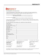
Страница 24: ...al components Ignition Control Boards Wiring Switches Fans Fan Control Module Battery Pack Remote Control Systems 1 Enamel Panels 1 Venting Venting Components 1 All Stainless steel surrounds 1 All Firebox Media Crystals Fire beads Volcanic Ceramic Spa Stones 1 All hardware 1 Mesh Glass Safety Barriers 1 Accent Light Bulbs 1 Glass Crazing 1 After the original warranty coverage for any of the parts ...

Страница 25: ...he general practice of FPI to charge for larger higher priced replacement parts and issue credit once the replaced component has been returned to FPI and evaluated for manufacturer defect If a consumer has a unit installed outside an accredited distributor dealer or pre approved service agent s service area or the closest approved service agent is situated more than thirty 30 kilometres from the i...

Страница 26: ...inor movement expansion and contraction of the steel is normal and is not covered under the terms of this warranty Freight damages for products or parts are not covered under the terms of the warranty Porcelain Enamel Absolute perfection is neither guaranteed nor commercially possible Any chips must be reported and inspected by the authorised selling dealer within three 3 days of installation Any ...

Страница 27: ...ed to at the option of the supplier one or more of the following i replacement of the goods or the supply of equivalent goods ii the repair of the goods iii the payment of the cost of replacing the goods or of acquiring equivalent goods or iv equivalent goods or v the payment of the cost of having the goods repaired b To the extent that services supplied by the supplier are services other than ser...

Страница 28: ...n services Fireplace Products Australia Pty Ltd 1 3 Conquest Way Hallam VIC Australia 3803 Phone 61 3 9799 7277 Fax 61 3 9799 7822 To obtain warranty service in Western Australia and or New Zealand please contact one of our authorised distributors in those areas Western Australia Air Group Australia 28 30 Division St Welshpool WA Australia 6106 Phone 08 9350 2200 Fax 08 9353 4225 New Zealand Aber ...

Страница 29: ...low in order for us to serve you better Warranty Registration Form or Register online immediately at the above Web Site Warranty Details Serial Number required Purchase Date required mm dd yyyy Product Details Product Model required Dealer Details Dealer Name required Dealer Address Dealer Phone Installer Date Installed mm dd yyyy Your Contact Details required Name Address Phone Email For purchase...

Страница 30: ...30 Regency FG38 FireGenie Freestanding Gas Stove ...

Страница 31: ...Regency FG38 FireGenie Freestanding Gas Stove 31 ...

Страница 32: ...me Address _______________________________________________ ___________________________________________________________________ Installer ____________________________________________________________ Phone ____________________________________________________________ Date Installed _______________________________________________________ Serial No ______________________________________________________...

Отзывы: