Regency F33 Скачать руководство пользователя страница 20

20

Regency

®

 F33-3 Freestanding Gas Stove

Regency Freestanding Gas

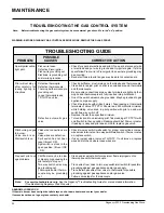
Note:  Before troubleshooting the gas control system, be sure external gas shut off is in the "on" position.

TROUBLESHOOTING THE GAS CONTROL SYSTEM

WARNING: BEFORE DOING ANY GAS CONTROL SERVICE WORK, REMOVE THE GLASS FRONT.

 POSSIBLE

     PROBLEM 

 CAUSES 

               CORRECTIVE ACTION

TROUBLESHOOTING GUIDE

Spark igniter will not 

light pilot.

Pilot will not stay lit 

after  carefully  fol-

lowing lighting in-

structions.

Pilot burning, no gas 

to burner.

Valve  knob  is  on. 

Wall switch is on.

Frequent  pilot  out-

age problems.


Piezo wire loose

Defective Piezo igniter.

Piezo wire grounding out.

Electrode is grounding out 

and/or wrong location.

Defective thermopile.

Defective thermocouple.

Thermopile/thermocouple 

grounding out.

Loose thermopile leads.

TP-THTP on valve.

Defective  automatic  gas 

valve.

Valve wire connections are 

loose.

Valve wires are defective.

Spill switch has not been 

reset (B-vent F/S).

Spill switch is stuck in the 

open position. (B-vent INS 

- F/S).

Pilot flame may be too low 

or blowing high causing the 

pilot safety to drop out.

Two way switch wires may 

be grounding out.

Thermopile and/or thermo-

couple  may  be  grounding 

out.

•  

Check for spark at electrode and pilot. If no spark, disconnect wire 

at electrode and put wire to ground and try igniter again. If still no 

spark follow Piezo wire to Piezo igniter to see where grounding may 

be occurring.

•  Bend electrode into pilot so gas may be able to contact spark.

•  Check pilot flame, must impinge on thermopile and thermocouple.

•  Clean and/or adjust pilot so pilot is enveloped around thermopile 

and thermocouple.

•  Be sure wire connections at gas valve terminals are tight and ther-

mopile and thermocouple are fully inserted into pilot bracket.

•  One of the switch wires may be grounded. May be grounded to gas 

appliance or gas supply.

•  Check thermopile with millivolt meter. Take reading at thermopile 

terminals of valve TP-TPTH. Should read 250 millivolts minimum 

while  holding  valve  knob  in  pilot  position  with  pilot  on  and  wall 

switch/two way switch off.

•  Replace if lower than specified minimum.

•  Turn valve knob to on including pilot. Take reading at TP-TPTH with 

on/off switch in the on position. Reading should be 100mv or greater. 

If reading is okay and pilot does not hold, replace gas valve.

•  Check two way switch/wall switch for proper connections. Jumper 

wire across terminals at two way switch/wall switch. If burner comes 

on, replace switch.

•  If okay, jumper wire at valve at TH-THTP.  If unit turns on, replace 

wires and/or check where loose wires are.

•  Clean and/or adjust pilot for maximum flame impingement on 

thermopile and/or thermocouple.

•  Trace wires from valve to two way switch/wall switch for possible 

grounding against gas appliance and/or gas supply.

•  Trace thermopile wires from valve to thermopile for possible 

grounding against gas appliance and/or gas valve.

•  Follow same steps for thermocouple.

Note:


For service technicians only

.

 See the Regency

®

 Troubleshooting Guide for more detailed information. 


(Troubleshooting Regency

®

 Gas Products)

MAINTENANCE


ABNORMAL OPERATION

If the main burner does not light but pilot stays on shut down heater and contact your dealer

If excessive carbon on logs or glass contact your dealer        


Содержание F33

Страница 1: ...lt an authorized installer service agency or the gas supplier FOR YOUR SAFETY Do not store or use gasoline or other flam mable vapours and liquids in the vicinity of this or any other appliance Installation and service must be performed by an authorized installer service agency or the gas supplier PLEASE KEEP THESE INSTRUCTIONS FOR FUTURE REFERENCE Owners Installation Manual LISTINGS AND CODE APPR...

Страница 2: ...u with all the warmth and charm of a woodstove at the flick of a switch The models F33 NG3 and F33 LPG3 have been approved by the Australian Gas Association for both safety and efficiency As it also bears our own mark it promises to provide you with economy comfort and security for many trouble free years to follow Please take a moment now to acquaint yourself with these instructions and the many ...

Страница 3: ...lation 12 Optional Wall Thermostat Installation 12 Thermostat Wire Table 12 Final Check 12 OPERATING INSTRUCTIONS Operating Instructions 13 Lighting Procedure 13 Shutdown Procedure 13 Copy of the Lighting Plate Instructions 14 MAINTENANCE Normal Operating Sounds of Gas Appliances 15 Maintenance Instructions 15 General Flue Maintenance 16 Log Replacement 16 Gold plated Doors 16 Glass Replacement 16...

Страница 4: ...on Grey Size 100 Sept 22 09 updated standard removed 2000 from As4553 Feb 3 10 Changed distributor address Sept 12 12 Updated Code Dec 24 13 Rev F updated E Aus address and formatting of code July 5 16 Updated with NZ address added Nov 8 16 Rev G Updated F33 unit name Electrical 240VAC 50Hz 1 0 amp max Serial Number 918 092g Model N2134 Regency Gas Fireplace 3 0mm 1 15mm 2 7mm 1 6mm AS4553 227 AGA...

Страница 5: ... the appliance to ensure the correct firing rate rate noted on label after burning appliance for 15 minutes BEFORE YOU START INSTALLATION AND REPAIR SHOULD BE DONE BY AN AU THORISED SERVICE PERSON THE APPLIANCE SHOULD BE INSPECTED BEFORE USE AND AT LEAST ANNUALLY BY AN AUTHORISED SERVICE PERSON MORE FREQUENT CLEANING MAY BE REQUIRED DUE TO EXCESSIVE LINT FROMCARPETING BEDDINGMATERIAL ETC ITISIMPER...

Страница 6: ...sessootingorcarboning that results in damage is not the responsibility of the manufacturer CLEARANCES TO COMBUSTIBLES The clearances listed below are MINIMUM distances Measure the clearance to both the appliance and the chimney connector The farthest distance is correct if the two clearances do not coincide For example if the appliance is set as indicated in one of the diagrams but the back wall i...

Страница 7: ...tom Shield or Pedestal 10 ConnecttheorangewirefromthespillswitchtotheBurnerON OFF switch 11 Re connect the fan harness plug 12 Secure the power cord with the supplied grommet at the back of the Bottom Shield or Pedestal LEG AND BOTTOM SHIELD ASSEMBLY These instructions apply to the black gold and nickel cast legs It will be easier to attach the legs to the stove if it is tipped on its back prefera...

Страница 8: ...open position Before trying to start up the unit make sure the red button on the spill switch is pushed in FLUEING REQUIREMENTS 100mm diameter flue is required in accordance with AS5601 2004 NZS 5261 or any relevant local building codes For altitudes above 610m we recommend that a minimum flue height of 3 6m is used WIRING CAUTION Label all wires prior to disconnection when servicing controls Wiri...

Страница 9: ... correct operating pressure For minimum and maximum supply pressure see the System Data table below Note During any pressure testing of the gas supply piping system that exceeds test pressures of 3 45 kPa this ap pliance and its individual shut off valve must be discon nected from the piping system If test pressures equal to or less than 3 45 kPa are used then this appliance can be isolated from t...

Страница 10: ...in the larger logs See diagrams 1 2 Carefully push the cross logs onto the pins Diagram 1 TEST FOR FLUE SPILLAGE This heater must be properly connected to a flue system WARNING Operation of this heater when not connected to a properly installed and maintained flue system or tampering with the flue safety shutoff system can result in carbon monoxide CO poisoning and possible death A spillage test m...

Страница 11: ...embers along the mesh ember tray but do not cover the burner ports Burner ports are the little holes on the top of the burner tube Pull off ember size pieces from the rock wool Gently place the pieces on top of the embers See diagram 3 Do not put the rock wool directly on the burner Close the door and turn the unit on as per lighting instructions Watch the flame to see if it flows smoothly around ...

Страница 12: ...battery in both receiver and the transmitter Install the receiver and cover in the wall The remote control is now ready for operation OPTIONAL WALL THERMOSTAT INSTALLATION A wall thermostat may be installed if desired Note Preferable if the thermostat is installed on an interior wall Use a CSA UCL or UL approved millivolt thermostat 250 750 millivolt rated A non anticipator type thermostat must be...

Страница 13: ...The FIRST FIRE in your stove is part of the paint curing process To ensure that the paint is properly cured it is recommended that you burn your fireplace for at least four 4 hours the first time you use it with the fan on When first operated the unit will release an odour caused by the curing of the paint and the burning off of any oils remaining from manufacturing Smoke detectors in the house ma...

Страница 14: ...ctly a fire or explosion may result causing propertydamage personalinjuryorlossoflife Improperinstallation adjustment alteration service or maintenance can cause injury or property damage Refer to the owner s information manual provided with this appliance For assistance or additional information consult a qualified installer service agency or gas supplier ...

Страница 15: ...ons Keep the burner and control compartment clean by brushing and vacuuming at least once a year When cleaning the logs use a soft clean brush as the logs are fragile and easily damaged 2 Clean appliance and door with a damp cloth never when unit is hot Never use an abrasive cleaner The glass should be cleaned with a gas fireplace glass cleaner when it starts to cloud up 3 The heater is finished i...

Страница 16: ...nt that you break your glass by impact purchase your replacement glass from an authorized Regency dealer only and follow our step by step instructions for replacement 1 Allow the stove to cool before removing or replacing glass 2 To remove the door from the stove remove the securing screw lo cated between the ashlip and the door then unfasten the latch 3 Remove gold hinge caps from door 4 Lift doo...

Страница 17: ...eckthepilotflames Correctflamepatternhasthree strong blue flames 1 flowing around the thermopile 1 around the thermocouple and 1 flowing across the burner it does not have to be touching the burner Note If you have an incorrect flame pattern contact your Regency dealer for further instructions MAINTENANCE Incorrect flame pattern will have small probably yellow flames not coming into proper contact...

Страница 18: ...Piezo Igniter by removing two 2 sheet metal screws 10 Loosen four 4 phillips head M5 valve mounting screws from un derside of firebox Push valve assembly forward on the teardrop slots and drop down 11 Disconnect Piezo wire To remove valve from valve assembly continue 12 Remove two 2 thermopile wires 13 Remove thermocouple with a 9 mm metric spanner 14 Remove pilot nut with an 11 mm spanner 15 Remo...

Страница 19: ...ate by removing 4 screws See diagram 1 Diagram 1 3 Remove valve cover plate by removing 2 screws 4 Disconnect the molex plug from inside the stove Note The 8 ground lug is a dedicated ground for mobile home use only 5 Loosen the four 8 32 x 1 2 screws provided into the nutserts as shown in diagram 3 NOTE Make sure the fan is supported as it may fall when the 4 screws are loosened Diagram 2 Ground ...

Страница 20: ...n and or adjust pilot so pilot is enveloped around thermopile and thermocouple Be sure wire connections at gas valve terminals are tight and ther mopile and thermocouple are fully inserted into pilot bracket One of the switch wires may be grounded May be grounded to gas appliance or gas supply Check thermopile with millivolt meter Take reading at thermopile terminals of valve TP TPTH Should read 2...

Страница 21: ...46 973 Door Handle Latch Assembly 10 910 714 Power Cord 240 V 11 910 006 Terminal Block 12 846 570 7 8 Door Gasket Repair Kit 13 846 918 Hinge Cap Gold Plated 2 set 14 Screw 10 24 x 3 4 Pan Head 15 Washer 1 4 split lock 16 Screw 10 24 x 1 2 Pan Head 17 471 031 Door Retainer Clip 19 948 101 Spring Handle Large 490 918 Packaged Fan Assembly 20 910 155 P Fan Blower Motor 240V 21 910 142 Thermodisc Fa...

Страница 22: ...10 035 Pilot Assembly 3 flame SIT LPG 67 904 604 Orifice 36 NG 904 390 Orifice 52 LPG 68 948 294 Burner NG 69 948 279 Burner LPG 70 Complete Burner Tray Assy SIT NG 71 Complete Burner Tray Assy SIT LPG 72 490 023 Front Log Deflector NG LPG 75 490 068 Rear Log Deflector Top LPG 79 460 011 Rear Burner Deflector Back NG 490 932 Complete Log Set 80 Front Log 81 Rear Log 82 Top Log each 902 151 Ember 9...

Страница 23: ... cord 121 Access Panel 140 850 127 Cast Legs Gold 850 126 Cast Legs Black 850 128 Cast Legs Brush Nickel 142 850 125 Steel Legs Pedestal Assembly 490 926 Complete Pedestal 100 948 216 Logo Plate Regency 102 904 257 Magnetic Catch Large 103 11 Pedestal Hinge 108 910 246 Burner ON OFF Switch 109 910 140 Fan Hi Off Low Switch 110 Strain Relief for power cord 123 Pedestal Blanking Plate 124 820 058F P...

Страница 24: ...omponents Ignition Control Boards Wiring Switches Fans Fan Control Module Battery Pack Remote Control Systems 1 Enamel Panels 1 Venting Venting Components 1 All Stainless steel surrounds 1 All Firebox Media Crystals Fire beads Volcanic Ceramic Spa Stones 1 All hardware 1 Mesh Glass Safety Barriers 1 Accent Light Bulbs 1 Glass Crazing 1 After the original warranty coverage for any of the parts abov...

Страница 25: ...eneral practice of FPI to charge for larger higher priced replacement parts and issue credit once the replaced component has been returned to FPI and evaluated for manufacturer defect If a consumer has a unit installed outside an accredited distributor dealer or pre approved service agent s service area or the closest approved service agent is situated more than thirty 30 kilometres from the insta...

Страница 26: ...movement expansion and contraction of the steel is normal and is not covered under the terms of this warranty Freight damages for products or parts are not covered under the terms of the warranty Porcelain Enamel Absolute perfection is neither guaranteed nor commercially possible Any chips must be reported and inspected by the authorised selling dealer within three 3 days of installation Any damag...

Страница 27: ...o at the option of the supplier one or more of the following i replacement of the goods or the supply of equivalent goods ii the repair of the goods iii the payment of the cost of replacing the goods or of acquiring equivalent goods or iv equivalent goods or v the payment of the cost of having the goods repaired b To the extent that services supplied by the supplier are services other than service...

Страница 28: ...rvices Fireplace Products Australia Pty Ltd 1 3 Conquest Way Hallam VIC Australia 3803 Phone 61 3 9799 7277 Fax 61 3 9799 7822 To obtain warranty service in Western Australia and or New Zealand please contact one of our authorised distributors in those areas Western Australia Air Group Australia 28 30 Division St Welshpool WA Australia 6106 Phone 08 9350 2200 Fax 08 9353 4225 New Zealand Aber Hold...

Страница 29: ...in order for us to serve you better Warranty Registration Form or Register online immediately at the above Web Site Warranty Details Serial Number required Purchase Date required mm dd yyyy Product Details Product Model required Dealer Details Dealer Name required Dealer Address Dealer Phone Installer Date Installed mm dd yyyy Your Contact Details required Name Address Phone Email For purchases ma...

Страница 30: ...30 Regency F33 3 Freestanding Gas Stove ...

Страница 31: ...Regency F33 3 Freestanding Gas Stove 31 ...

Страница 32: ...__________________________ Installer ____________________________________________________________ Phone ____________________________________________________________ Date Installed _______________________________________________________ Serial No ___________________________________________________________ Copyright 2019 FPI Fireplace Products International Ltd All rights reserved ...

Отзывы: