background image

WARNING:  
If the information in these instructions are not followed ex-
actly, a fi re or explosion may result causing property damage, 
personal injury or loss of life. 

FOR YOUR SAFETY
Do not store or use gasoline or other fl ammable vapors and 
liquids in the vicinity of this or any other appliance.

Installation and service must be performed by a qualifi ed 
installer, service agency or the gas supplier.

FOR YOUR SAFETY
What to do if you smell gas:

Do not try to light any appliance

Do not touch any electrical switch: 
do not use any phone in your build-
ing.

Immediately call your gas supplier 
from a neighbour's phone. Follow 
the gas supplier's instructions.

If you  cannot reach your gas 
supplier, call the fi re department.

FPI FIREPLACE PRODUCTS INTERNATIONAL LTD.  6988 Venture St., Delta, BC  Canada, V4G 1H4

919-099

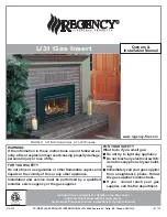
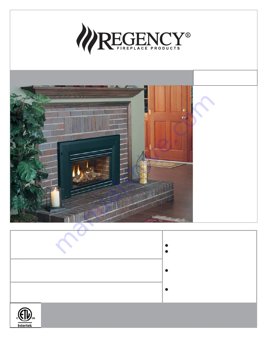
MODELS:   U31-NG3 Natural Gas   U31-LP3Propane

10/17/12

U31 Gas Insert

Owners & 

Installation Manual

www.regency-fi re.com

Tested by:

Installer: Please complete the details on the back cover 

and leave this manual with the homeowner.

Homeowner: Please keep these instructions for future reference.

Содержание Energy U31

Страница 1: ...Do not try to light any appliance Do not touch any electrical switch do not use any phone in your build ing Immediately call your gas supplier from a neighbour s phone Follow the gas supplier s instructions If you cannot reach your gas supplier call the fire department FPI FIREPLACE PRODUCTS INTERNATIONAL LTD 6988 Venture St Delta BC Canada V4G 1H4 919 099 MODELS U31 NG3 Natural Gas U31 LP3Propane...

Страница 2: ...de you with all the warmth and charm of a fireplace at the flick of a switch The models U31 NG3 and U31 LP3 of this series have been approved by Warnock Hersey for both safety and ef ficiency As it also bears our own mark it promises to provide you with economy comfort and security for many trouble free years to follow Please take a moment now to acquaint yourself with these instructions and the m...

Страница 3: ...3 DIMENSIONS Note Oversize faceplate is 44 x 28 1118 mm x 711mm Low Profile Faceplate Dimensions 40 3 4 1036mm 35 15 16 912mm 27 15 16 710mm 14 7 8 378mm 22 559mm 23 15 16 607mm 10 7 8 276mm Standard size shown custom size also available ...

Страница 4: ...ON For Your Safety 7 Specifications 8 Installation into a Solid Fuel Fireplace 8 General Safety Information 8 Installation Checklist 9 Materials Required 9 Minimum Fireplace Clearances 9 Clearances to Combustibles 9 Conversion to Propane Kit 10 Gas Connection 10 High Elevation 10 Draft Hood Connection 10 Venting 11 Combustion Ventilation 11 Gas Pressure Test 11 Gas Insert Aeration System 11 Test f...

Страница 5: ... Installer l appareil selon les codes ou règlements locaux ou en l absence de tels règlements selon les codes d installation ANSI Z223 1 National Fuel Gas Code ou CSA B149 1 en vigueur Installer l appareil selon la norme CAN CSA Z240 Série MM Maison mobiles ou CAN CSA Z240 VC Véhicules de camping ou la norme 24 CFR Part 3280 Manufactured Home Construction and Safety Standard Si ces normes ne sont ...

Страница 6: ...ly in line with the exhaust vent terminal for the horizontally vented gas fueled heating appliance or equipment The sign shall read in print size no less than one half 1 2 inch in size GAS VENT DIRECTLY BELOW KEEP CLEAR OF ALL OBSTRUCTIONS 4 INSPECTION The state or local gas inspector of the side wall horizontally vented gas fueled equipment shall not approve the installation unless upon inspectio...

Страница 7: ...PPLIANCE SHOULD BE LOCATED OUT OF TRAFFIC AND AWAY FROM FURNITURE AND DRAPERIES WARNING FAILURE TO INSTALL THIS APPLIANCE CORRECTLY WILL VOID YOUR WARRANTY AND MAY CAUSE A SERIOUS HOUSE FIRE YOUNG CHILDREN SHOULD BE CARE FULLY SUPERVISED WHENTHEY ARE IN THE SAME AREA AS THE APPLI ANCE TODDLERS YOUNG CHILDREN AND OTHERS MAY BE SUSCEPTIBLE TO ACCIDENTAL CONTACT BURNS A PHYSICALBARRIERSISRECOMMEND ED...

Страница 8: ...ce 5 This appliance is Listed for bedroom installa tions InCanadaroomheatersmustbeinstalled with a Listed Millivolt Thermostat Some areas may have further requirements check local codes before installation 6 This unit is not approved for installation into a mobile home 7 Always connect this insert to a vent system venting to the outside of the building envelope Nevervent toanotherroomorinsideabuil...

Страница 9: ...Optional Wall Thermostat 14 Final check Before leaving this unit with the customer the installer must ensure that the appliance is firing correctly This includes a Clocking the appliance to ensure the correct firing rate b Adjusting the primary air if required to ensure that the flame does not carbon c Ensuring that the appliance is venting correctly MATERIALS REQUIRED No electrical power supply i...

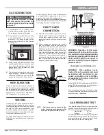
Страница 10: ... Pull off the pilot cap to expose the pilot orifice 18 Unscrew the pilot orifice with the allen key and replace with the LP pilot orifice in the kit 19 Replace Burner Tray and reverse steps 5 to 1 20 Adjust the burner aeration setting to 3 8 to 3 8 as required for the best flame picture Fig 1 9 R e m o v e t h e b l a c k protection cap by hand fromthehi lowknob Fig 1 Fig 2 12 Flip the screw Fig 3...

Страница 11: ...ority Air for combustion is drawn in through the front of the unit therefore the front of the unit must be kept clear of any obstructions GAS PRESSURE TEST Theunitispresettogivethecorrectgasinputatthe specified manifold pressures shown on the label The maximum gas manifold pressure is Natural Gas 3 5 w c Propane 10 w c The manifold pressure is controlled by a regulator built into the gas control a...

Страница 12: ...HIS SWITCH OPTIONAL BRICK PANEL 1 Unwrap the brick pattern panels from the pro tective wrapping 2 Remove the glass front if it is already installed 3 Put the rear brick panel flat against the back of the unit TEST FOR FLUE SPILLAGE A spillage test must be made before the installed unit is left with the customer Follow the procedure below 1 Start all exhaust fans in the home and then close all exte...

Страница 13: ...179 P Vermiculite k 946 669 Platinum Embers supplied with packaged manual Note Install Optional Brick Panels prior to installing logs 1 Carefully remove the logs from the box and unwrap them The logs are fragile handle with care do not force into position 2 Sprinkle the vermiculite around the firebox base Take some of the embers approx 1 3 of the bag and sprinkle over the vermiculite 3 Place Rear ...

Страница 14: ...B 02 45 and across the cutout on Log A 02 43 Cutout Pin Cutout Notch 8 Position notch in Front Right Log F 02 48 on Log E 02 47 and push the bottom right edge against the bracket on the burner tray and the front edge of the rear burner Notch Bracket D 02 46 E 02 47 F 02 48 C 02 56 A 02 43 B 02 45 A 02 43 B 02 45 E 0 2 4 7 Logs A 02 43 C 02 56 and B 02 45 in position C 02 56 5 Place the Middle Left...

Страница 15: ...st the bracket and the front edge of the rear burner Side View 11 Separate platinum embers and place on and around the embers and rockwool on the burner tray Avoid stacking platinum embers 12 Test fire to ensure proper light off make sure flame flows smoothly from one end of burner to the other If there is any flame hesitation check that area for any blockage of the burner port The 02 refer number...

Страница 16: ...onnectors provided join the left side trim with the ON OFF switch to the top trim Diagram 2 Connect the right side trim to the top trim 4 Place the trim on the assembled faceplate panels aligning the wire connections from the switches with the notch on the left side panel 5 Connect the fan switch wires by taking the black and red wires with the male ends in the grey harness and connect them with t...

Страница 17: ...ips at the top corners of the glass Secure glass clips with the screws provided Do not over tighten as this could break the glass 5 Slide in the top glass trim under the spring clips 1 The Top Louver is held in place by friction fit if the Louver needs to be adjusted bend the bracket out as shown in the diagram Line up hooks on mesh guard with slots on unit Slide mesh guard down into slots until s...

Страница 18: ... and should be plugged directly into a properly grounded three prong receptacle Do not cut or remove the grounding prong from this plug Caution Ensure that the wires do not touch any hot surfaces and are away from sharp edges Burner ON OFF Piezo Ignitor To Pilot Gas Remote Transmitter Optional Thermostat Millivolt Optional Remote Receiver Optional Millivolt ON OFF Regency Vent Spill Switch Auto Re...

Страница 19: ...to side trim 2 Lift unit up slightly and push down on the corners of the Bottom Trim Bracket and slide under unit Unit should touch tabs on Bottom Trim Bracket Bottom Trim Bracket Push in Corners 3 Completely secure the full screen door to the unit by securing 4 screws to the Left and Right Side Trims NOTE When mounting the full screen door to the unit the inside flange of the side trims are to fi...

Страница 20: ...with the wire connectors from the fan speed control Place clips over wires and tuck into side trim for gas connection Self adhesive wire clip ON OFF switch wires to ON OFF switch wires to Fan switch connectors Fan Speed Switch Rear View IMPORTANT NOTE When using the Surround the unit must be set 1 further into the fireplace than the standard faceplate installation See the diagrams below for the co...

Страница 21: ... the Faceplate Push down to secure Tug on the Sur round to ensure it is securely locked in place Backside of Sur round Shown Hooks Faceplate Slots Surround Faceplate 4 Secure the Faceplate by sliding the slots in the Faceplate into the flanges on the left and right side Faceplate Trim Brackets Once the Faceplate is in place secure using 2 screws per side Faceplate Left Side Faceplate Bracket Trim ...

Страница 22: ...the control box Diagram 6 Diagram 7 4 Tuck the wires into the clip to keep them away from the insert using the clip provided Attach the clip to the rear of the faceplate to en sure that the wires do not touch the side of the unit The power cord should be run behind the inner faceplate panel 5 Install the on off switch fan speed control box to the left hand bottom leg of the inner faceplate Control...

Страница 23: ...ns over glass door in locations shown below in Diagram 11 7 Clip the right side air chamber clip as shown below in Diagram 8 8 Attach 2 brackets near the bottom of the unit with one screw as shown below in Diagram 9 left and right brackets are inter changeable 9 Attach Regency logo to bottom louver Install bottom louver by hanging louver on brackets installed in step 8 Final Install Diagram 8 Diag...

Страница 24: ...eries in the receiver Install the receiver and its cover in the wall Switch the remote receiver to remote mode The remote control is now ready for operation FINAL CHECK Before leaving this unit with the customer the installer must ensure that the appliance is firing correctly This includes 1 Clocking the appliance to ensure the correct firing rate rate noted on label at 15 minutes 2 If required ad...

Страница 25: ...glass heats up DO NOT BURN THE APPLI ANCE WITHOUT THE GLASS FRONT IN PLACE NORMAL OPERATING SOUNDS OF GAS APPLIANCES when ON This sound will increase or decrease in volume depending on the speed setting of your fan speed control Burner Tray The burner tray is positioned directly under the burner tube s and logs and is made of a differ ent gauge material from the rest of the firebox and body Theref...

Страница 26: ...requires little maintenance and need only be cleanedwithadampcloth DONOTuseabrasive materials or chemical cleaners as they may harm the finish and void the warranty Cleananyfingerprintsoff beforeturningthe unit on If the top louvers start to discolour check the door gasket seal and replace if necessary LOG REPLACEMENT The unit should never be used with broken logs Turn off the gas valve and allow ...

Страница 27: ...placing the Burner Tray slide the aeration adjustment rod through the opening in the front of the Valve Assembly To remove fan 1 Turn the unit off and allow it to cool to room temperature 2 Unplug or disconnect power source to stove 3 Remove glass front see page 11 4 Remove logs 5 Remove brick panels 6 Remove the Grate by removing the screws on each side of the grate 7 Remove the Burner Tray by re...

Страница 28: ...e 17 Wire Holder Clip 18 Strain Relief 19 Grommet for Power Cord 20 400 024 Air Channel 21 402 922 Flush Louvers Set Gold Black 402 920 Flush Louvers Set Black 402 924 Flush Louvers Set Steel Black 33 404 901 Brick Panel Set Standard Brown 404 902 Brick Panel Set Standard Red Brick Panel Back Main Assembly Part Description Part Description 34 Brick Panel Left Side 35 Brick Panel Right Side 36 400 ...

Страница 29: ... High Altitude 60 402 526 Grate Assembly 62 404 525 Burner Assembly NG LP 63 910 048 Pilot Assembly NG 4 flame convertible top 910 049 Pilot Assemby LP 4 flame convertible top 67 Firebox Base 69 402 935 Log Set 402 572 Ember Package 70 Air Channel 72 Glass Trim Retainer 73 Firebox back and top 74 Glass Gasket Retainer 75 Firebox Baffle 76 400 090 Brick Clip 77 Fan Access Plate 78 Thermodisc Bracke...

Страница 30: ...h Door 402 515 P Complete Flush Front 150 936 243 Door Frame Gasket 7 8 153 Glass Side Trim 154 Flush Glass 155 402 046 Glass Support Trim Black 156 936 238 Flush Glass Gasket 157 Screw 10 24 x 1 2 158 402 033 Flush Glass Bracket 159 936 233 3 4 Rope Gasket Not available as a replacement part ...

Страница 31: ...dard 92 Faceplate Top Standard 93 Faceplate Side Left Assy Standard 402 532 Trims Pkg Standard 94 Faceplate Trim Right Standard 95 Faceplate Trim Top Standard 96 Faceplate Trim Left Assy Standard 402 933 Molded Faceplate Complete Set 141 Faceplate Side Right Molded 142 Faceplate Top Molded 143 Faceplate Side Left Assy Molded 144 402 044 Mounting Bracket Right 145 402 045 Filler Bracket 146 402 043...

Страница 32: ...32 Regency U31 3 Gas Fireplace Insert PARTS LIST ...

Страница 33: ...gency U31 3 Gas Fireplace Insert 33 PARTS LIST 1 2 4 3 5 LOW PROFILE FACEPLATE Part 403 954 Description 1 Back plate Assembly 2 Bottom Louver 3 Right mounting bracket 4 Left mounting bracket 5 Front Frame ...

Страница 34: ...34 Regency U31 3 Gas Fireplace Insert NOTES ...

Страница 35: ...art be returned to the distributor or agent Transportation Prepaid if requested Porcelain Enamel Absolute perfection is either guaranteed nor commercially possible Any chips must be reported and inspected by an authorized dealer within three days of installation Reported damage after this time will be subject to rejection It is the general practice of FPI to charge for larger higher priced replace...

Страница 36: ...________________________________________________________ Phone ___________________________________________________________ Date Installed ______________________________________________________ Serial No __________________________________________________________ Register your Regency warranty online www regency fire com Reasons to register your product online today View and modify a list of all you...

Отзывы: