background image


I1205  |    9

9

installation

INSTALLING

YOUR INSERT

SAFETY NOTE:

 The insert is very heavy and 

will require two or three people to move it into 

position. The insert can be made a little lighter 

by removing the cast iron door by opening it and 

lifting it off its hinges. Be sure to protect your 

hearth extension with a heavy blanket or carpet 

scrap during the installation.

NOTE: 

You will be required to purchase either 

the  standard  or  offset  6"  diameter  (152mm) 

flue adaptor that is best suited for the specific 

installation.

List of Tools needed;

 - Pull Rod (included with insert)

 - 1/2” socket / ratchet

 - 3/8 open face wrench 

1)

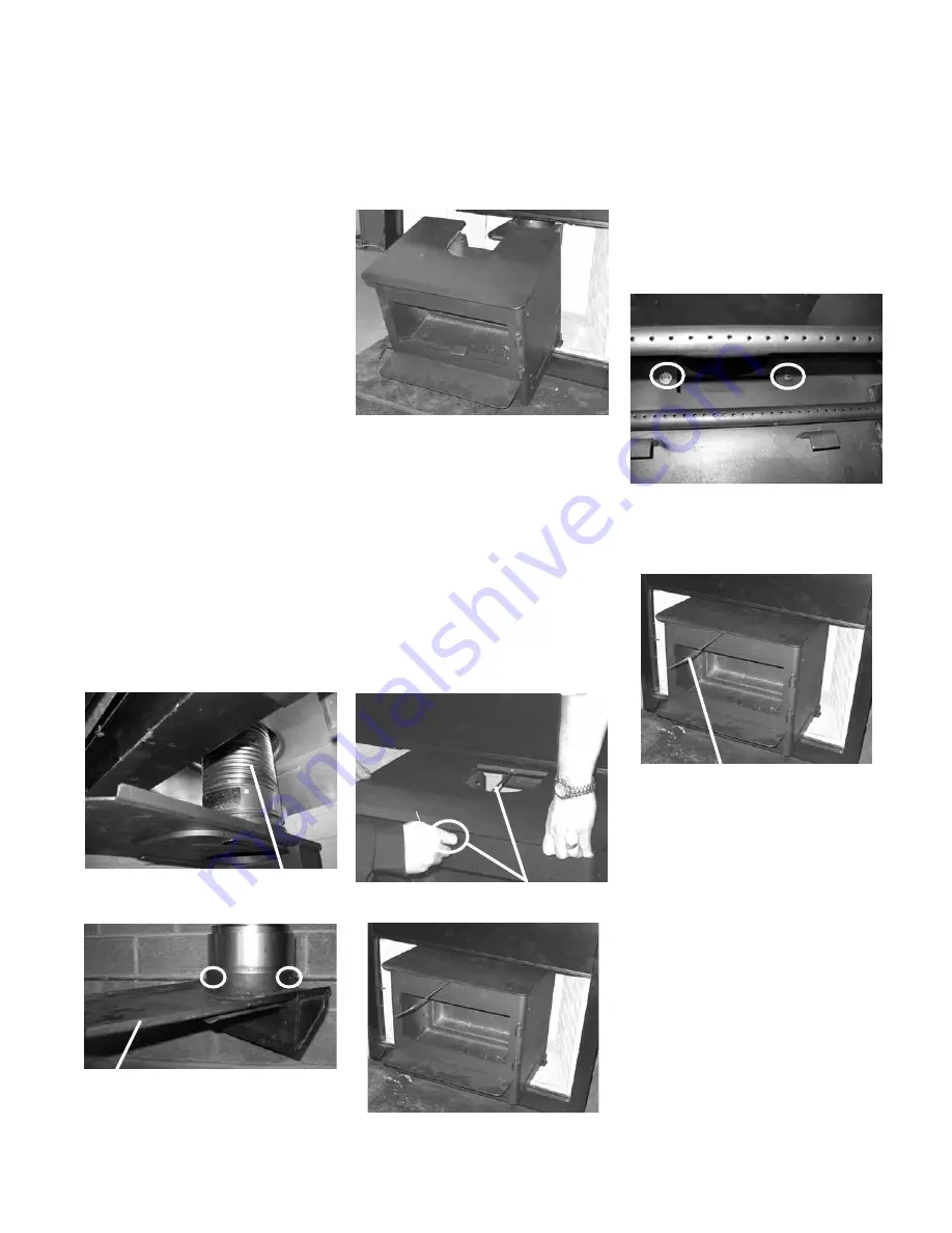
   Install  flex  liner  into  existing  chimney  as 

per liner manufacturer’s specifications. See 

diagram 1.

2)

   Install the required flue adaptor onto the end 

of the flex liner.  Secure the adaptor using 

3 screws - 1 on the front, left and right side 

as shown in diagram 2.


Alignment of the flue adaptor can be critical 

during the install, it is recommended that the 

flex liner be left as compressed as possible.  

Before inserting the unit the adaptor should 

hang, when level, slightly above the required 

height. 

Secure adaptor using 3 screws - 1 in the 

front and 1 each on the left and right side.

3) 

  Install  the  unit  by  first  setting  the  rear  of 

the  unit  into  the  fireplace.  See  diagram 

3. Ensure that the unit is centered in the 

existing fireplace and lined up with the flue 

adaptor.


4)

   Slide the unit back until the flue adaptor is 

slightly engaged.  

5

)   At this point it is recommended to level the 

unit and ensure that the leveling bolts rest 

on the surface of the fireplace. This will keep 

the adaptor from binding as the unit is slid 

into position. 

6) 

 Insert the provided pull rod through the 

hole in the top center of the unit. Secure 

the threaded end into the flue adaptor as 

shown in diagram 4. While sliding the unit 

into place pull on the rod to ensure that 

the flue adaptor is properly engaged. See 

diagram 5. 

Pull Rod

7)

   Ensure that the unit is still level. 

8)

   To complete the installation and to ensure a 

secure fit and connection of the flue adaptor 

to the insert, it is essential that the two bolts, 

flat  washers  and  lock  washers  (supplied 

with  packaged  manual)  be  installed  and 

tightened using a 1/2" socket as shown in 

diagram 6. This prevents the possibility of 

creosote drip and exhaust gas leakage.

9)

   Remove the pull rod from the top center of 

the fireplace. See diagram 7.

10)

 Re-install the door if removed prior to 

installation.

NOTE: The pull rod should not be thrown 

away. It should be kept if the stove 

is ever needed to be removed from 

the fireplace.

Flex Liner

Pull Rod In Place

Pull Rod

Diagram 1

Diagram 2

Diagram 3

Diagram 4

Diagram 5

Diagram 6

Diagram 7

Flue Adaptor

Содержание Classic I1205M

Страница 1: ...e fr MODÈLE I1205S Poêle encastrable au bois Classic I1205M 12 04 18 MANUEL D INSTALLATION ET D UTILISATION Installateur Merci de remplir la dernière page de ce manuel et de laisser le manuel au client Propriétaire Merci de conserver ce manuel pour référence ultérieure www regency fire com ...

Страница 2: ... ou si des pièces sont retirées de l appareil La réglementation fédérale interdit de faire fonctionner un tel appareil si les consignes d utilisation contenues dans le présent manuel ne sont pas respectées ATTENTION BRÛLERUNIQUEMENTDUBOISNON TRAITÉ LACOMBUSTIONDE TOUTAUTREMATÉRIAUCOMMELESAGENTSDECONSERVATION DU BOIS LES FEUILLES DE MÉTAL LE CHARBON LE PLASTIQUE LES DÉCHETS LE SOUFFRE OU L HUILE PE...

Страница 3: ...acement du déflecteur de fumée en acier inoxydable 11 Installation de la façade de la bordure du ventilateur de la garniture inférieure de la façade du support de ventilateur en option 12 15 Ventilateur 16 Assemblage des briques 17 Poignée de porte 17 Installation du déflecteur de cheminée en briques et des tubes d air secondaire 17 Régulateur de tirage 17 CONSIGNES D UTILISATION 18 20 Bois séché ...

Страница 4: ...ONLY WITH CERAMIC GLASS 5MM INSPECT AND CLEAN CHIMNEY FREQUENTLY UNDER CERTAIN CONDITIONS OF USE CREOSOTE BUILDUP MAY OCCUR RAPIDLY DO NOT OVERFIRE IF INSERT GLOWS YOU ARE OVER FIRING MINIMUM CLEARANCES TO COMBUSTIBLE MATERIALS MEASURED FROM INSERT BODY INSTALL ONLY ON A NON COMBUSTIBLE HEARTH RAISED F 1 5IN 38MM ABOVE AN ADJACENT COMBUSTIBLE FLOOR COMBUSTIBLE FLOOR MUST BE PROTECTED BY NON COMBUS...

Страница 5: ... POUR CONDUIT DE CHEMINÉE STANDARD ADAPTATEUR STANDARD 171 932 de 6 po 152mm de dia 8 1 4 po entre l axe central de la buse 13 9 16 345 mm po et l arrière de la façade Les encastrables Regency sont conçus pour accueillir un conduit de 5 5 po 140 mm ou 6 po 152 mm ...

Страница 6: ...4 578mm 18 3 4 476mm 19 1 2 496mm 22 3 4 578mm 21 3 8 543mm 22 3 4 578mm 21 1 4 540mm 16 7 8 428mm 20 1 8 511mm ADAPTATEUR DÉCALÉ 171 936 de 6 po 152 mm de dia et l arrière de la façade 16 15 16 430 mm po 12 3 4 po entre l axe central de la buse Les encastrables Regency sont conçus pour accueillir un conduit de 5 5 po 140 mm ou 6 po 152 mm ...

Страница 7: ... service d inspection municipal L obtention d un permis peut être requise avant de procéder à l installation de l encastrable À noter que certaines règles ou codes locaux peuvent prévaloirsurcertainesprocéduresdétaillées dans ce manuel AVERTISSEMENT Une mauvaise installation constitueunedesprincipalescausesd accident Vérifier tous les codes locaux du bâtiment ainsi que les normes de sécurité avant...

Страница 8: ...abriqué sont précisés ci dessous H CHOISIR LE BON REVÊTEMENT DE PROTECTION DE PLANCHER Laprotectiondeplancherspécifiqueàcetteinstalla tion doit être faite d un matériau de 3 8 po 18 mm d épaisseur ave un facteur Kelvin de 0 84 L alternative proposée est une brique de 4 po 102 mm d un facteur C de 1 25 sur un panneau minéral de 1 8 po 3 mm avec un facteur K de 0 29 Étape a Utiliser la formule ci de...

Страница 9: ...sur le côté gauche et 1 sur le côté droit 3 Installer l appareil en plaçant d abord l arrière de l appareil dans l enchâssure du foyer Voir schéma 5 S assurer que l appareil est centré dans le foyer existant et aligné avec l adaptateur 4 Glisser l appareil vers l arrière jusqu à ce que l adaptateur soit légèrement coincé 5 À ce point de l installation il est recommandé de mettre l appareil à nivea...

Страница 10: ...uit pleine longueur aucune trappe de ra monage requise Au Canada ce foyer encastrable doit être in stalléavecunegainedecheminéecontinuede 5 5po 140mm ou6po 152mm dediamètre s étendant de l encastrable au sommet de la cheminée La gaine de cheminée doit être conforme aux exigences de classe 3 du CAN ULC S635ouduCAN ULC S640 Standardfor Lining Systems for New Masonry Chimneys 4 Sileplancherdufoyerest...

Страница 11: ... haut pour le sortir Installer un nouveau déflecteur et serrer les boulons à la main S assurer que l emplacement du déflecteur est correct avant de serrer les boulons AVERTISSEMENT L utilisation de l appareil sans que le déflecteur de fumée soit correctement installé entraînera l annulation de la garantie Le déflecteur est installé par l ouverture de la porte dans l emplacement indiqué sur le sché...

Страница 12: ...ENTILATEUR EN OPTION Dimensions de la façade standard illustrée avec la garniture inférieure de la façade le support du ventilateur Dimensions de la façade grand format illustrée avec la garniture inférieure de la façade le support du ventilateur Assemblage de la façade INSTALLATION DE LA FAÇADE DE LA BORDURE DU VENTILATEUR DE LA GARNITURE IN FÉRIEURE DE LA FAÇADE DU SUPPORT DE VENTILATEUR EN OPTI...

Страница 13: ...ale de la f çade a Schéma 2 Vue arrière 4 Poser les garnitures supérieure et latérales de la façade une fois as semblées sur l encastrable en veillant à passer la tige du régulateur de tirage dans l ouverture prévue à cet effet Placer également les encoches de la façade latérale vis à vis les boulons dans les brides de montage schéma 3 5 Mesurer la distance entre l âtre et le bas du côté de la gar...

Страница 14: ... sa bordure sur l encastrable en veillant à aligner les encoches de la garniture latérale de la façade sur les boulons hexagonaux des brides de montage Serrer ces derniers pour fixer le tout en place Schéma 5 Schéma 6 Foyer illustré avec la garniture inférieure de la façade en option Installation d une bordure de finition pour façade standard ou grand format Bordure noire fournie avec façade stand...

Страница 15: ...sous 18 Fixer la garniture inférieure de la façade à la façade à 3 côtés à l aide des 4 boulons rondelles fournis 19 Mettre de côté les deux bordures de finition latéralesfournies avec les façades standard grand format et les remplacer par les nouvelles bordures plus longues fournies avec la garniture inférieure de la façade et le support du ventilateur Les couper à la longueur voulue 20 Glisser l...

Страница 16: ...dres 2 Faire glisser les supports dans les attaches Ajuster la tension de ces dernières au besoin en augmentant ou en diminuant leur espace ment 3 S assurer que le câble électrique du ventilateur n est en contact avec aucune surface chaude Ne pas allumer le ventilateur avant que l encastrable n ait atteint sa température de fonctionnement ou au moins 30 minutes après l allumage de l appareil Insta...

Страница 17: ...liser une pince étau ou une paire de tenailles pour le maintenir solidement et l enfoncer au moyen d unmarteau Unajustementserrél empêchera de se déplacer pendant le fonctionnement de l appareil 2 Installer le déflecteur en briques de gauche en le glissant par dessus les tubes d air avant puis le pousser jusqu au fond de la chambre de combustion 3 Basculer le déflecteur de gauche vers le haut et l...

Страница 18: ...ger de la pluie mais ne pas recouvrir les côtés Les bois plus mous ex pin épinette et peuplier tremble s ils sont coupés fendus et bien cordés au début du printemps seront prêts pour l automne Les bois très durs ex chêne et érable surtout les gros morceaux peuvent exiger une année entière pour sécher suffisamment Le séchage peut prendre encore plus de temps dans un climat humide Il y a plusieurs m...

Страница 19: ... peut endommager la peinture Faire donc des feuxàintensitémodéréeaucoursdespremiers jours 8 Ne rien poser sur le dessus du poêle pendant la période de cuisson Cela pourrait endom mager le fini de la peinture 9 Au cours des premiers jours il pourra être plus difficile d allumer un feu Plus la brique réfractaire et la cheminée en maçonnerie s assècheront siapplicable pluslapuissance du tirage augmen...

Страница 20: ...surchauffe Arrêter d ajouter du combustible et fermer le régulateur de tirage La surchauffe de l appareil peut entraîner des dommagesimportantscommedesdéformations ou une corrosion prématurée de l acier Une surchauffeentraîneral annulationdelagarantie 8 Ne pas laisser s accumuler de créosote ou de suie dans le système de la cheminée Inspecter etfaireramonerlacheminéeàintervallesréguli ers 9 Le poê...

Страница 21: ...t de la porte se comprime après plusieursfeux Leretraitdesrondellesd écartement commeillustrésurleschémaci dessous permettra de rapprocher le loquet de l encadrement de porte pour renforcer l étanchéité Retirer puis remettre en place les écrous et la rondelle comme indiqué Rondelles d écartement ENTRETIEN DE LA VITRE Ne pas nettoyer la vitre lorsqu elle est chaude Lais ser la vitre refroidir avant...

Страница 22: ...6 846 570 Ensemble joint de la porte densité moyenne 17 846 918 Capuchons de charnières 2 jeu Doré 19 948 101 Poignée à ressort Large dorée 20 948 102 Poignée à ressort Petite dorée 170 915 Dispositif du ventilateur 24 910 157 P Moteur du ventilateur 25 910 678 Câble électrique 120 Volts 27 910 142 Thermodisque du ventilateur 28 910 140 Commutateur de vitesse du ventilateur HI OFF LOW 3 positions ...

Страница 23: ...rand format Noir 171 926 Jeu de garnitures Grand format Cuivre 171 572 Jeu de garnitures Grand format Noir 171 928 Piècedelabaseetsupportduventilateur Standard 171 930 Pièce de la base et support du ventilateur Grand format 60 Façade Côté droit Standard Grand format 61 Façade Côté gauche Standard Grand format 62 Façade dessus Standard Grand format 64 Façade bas monobloc 65 Support du ventilateur N...

Страница 24: ...eu de briques complet 70 Brique Standard pleine taille 1 1 4 po x 4 1 2 po x 9 po 76 Brique partielle 1 1 4 po x 2 po x 9 po 81 Brique partielle 1 1 4 po x 1 1 4 po x 9 po 84 Brique partielle 1 1 4 po x 4 1 2 po x 8 po 85 Brique partielle 1 1 4 po x 4 1 4 po x 8 po Non disponibles en pièces de remplacement ...

Страница 25: ...Encastrable au bois Regency I1200 25 notes ...

Страница 26: ...es chambre de combustion contours portes panneaux etc 3 Composants électriques ventilateur câblage interrupteurs etc 2 Vitre fissures 1 Dispositif catalyseur 6 ans prorata Évacuation Cheminée 1 Écrans de protection 1 Conditions La présente garantie couvre uniquement les vices de fabrication ou les défauts des composants assemblés à l usine de FPI sauf indication contraire énoncée dans la présente ...

Страница 27: ...ue d entretien ou une évacuation inadéquate un approvisionnement insuffisant en air de combustion l utilisation de produits chimiques corrosifs ex chlorine sel air etc les briques réfractaires fond parois latérales ou base le manque d étanchéité des portes ou des vitres ni tout autre système d étanchéité installé en usine Cette Garantie à Vie Limitée ne s applique pas aux problèmes de dysfonctionn...

Страница 28: ...RÉSENTE GARANTIE SPÉCIFIÉE LA DURÉE DE TOUTE GARANTIE IMPLICITE EST LIMITÉE À LA DURÉE DE LA GARANTIE EXPLICITE TEL QU INDIQUÉ CI DESSUS SI LES GARANTIES IMPLICITES NE PEUVENT PAS ÊTRE EXCLUES ALORS CES GARANTIES SONT LIMITÉES EN DURÉE À LA DURÉE DE LA PRÉSENTE GARANTIE Certains États aux États Unis n autorisent pas qu une limite soit fixée à la durée d une garantie implicite ou autorisent l exclu...

Страница 29: ...que nous puissions vous offrir le meilleur service possible Formulaire d enregistrement de la garantie ou enregistrement en ligne à l adresse web mentionnée ci dessus Informations sur la garantie Numéro de série obligatoire Date d achat obligatoire mm dd yyyy Informations sur le produit Type et modèle obligatoire Informations sur le détaillant Nom du détaillant obligatoire Adresse du détaillant No...

Страница 30: ...30 Encastrable au bois Regency I1200 garantie ...

Страница 31: ...Encastrable au bois Regency I1200 31 ...

Страница 32: ...teur _________________________________________________________ No de téléphone ____________________________________________________ Dated installation ___________________________________________________ No de série _________________________________________________________ Regency est une marque déposée de FPI Fireplace Products International Ltée Copyright 2018 FPI Fireplace Products International...

Страница 33: ...Canada V4G 1H4 918 998e I1205S Wood Insert 01 30 18 Owners Installation Manual Tested by Installer Please complete the details on the back cover and leave this manual with the homeowner Homeowner Please keep these instructions for future reference www regency fire com ...

Страница 34: ...the chimney is within the building envelope and fully lined It is against federal regulation to operate this wood heater in a manner inconsistent with operating instructions in this manual or if any parts are removed It is against federal regulation to operate this wood heater in a manner inconsistent with operating instructions in this manual CAUTION BURN UNTREATED WOOD ONLY OTHER MATERIALS SUCH ...

Страница 35: ...lation Into a Factory Built Fireplace 10 Stainless steel smoke deflector Installation 11 Faceplate Trim Optional 12 Bottom Faceplate Fan Support Installation 12 Fan Blower 16 Door Handle 17 Firebrick Assembly 17 Draft Control 17 Brick Flue Baffle Secondary Air Tube Installation 17 Screen Door 18 OPERATING INSTRUCTIONS First Fire 18 Fan Operation 19 Ash Disposal 19 Some Safety Guidelines 19 MAINTEN...

Страница 36: ...EL ONLY DO NOT USE GRATE OR ELEVATE FIRE BUILD WOOD FIRE DIRECTLY ON HEARTH OPERATE WITH FEED DOOR CLOSED OPEN TO FEED FIRE ONLY REPLACE GLASS ONLY WITH CERAMIC GLASS 5MM INSPECT AND CLEAN CHIMNEY FREQUENTLY UNDER CERTAIN CONDITIONS OF USE CREOSOTE BUILDUP MAY OCCUR RAPIDLY DO NOT OVERFIRE IF INSERT GLOWS YOU ARE OVER FIRING MINIMUM CLEARANCES TO COMBUSTIBLE MATERIALS MEASURED FROM INSERT BODY INS...

Страница 37: ...I1205 5 5 dimensions WITH STANDARD FLUE ADAPTOR 6 152mm Diameter STANDARD FLUE ADAPTOR 171 932 ...

Страница 38: ...60mm 12 3 4 324mm 17 3 4 451mm 22 3 4 578mm 18 3 4 476mm 19 1 2 496mm 22 3 4 578mm 21 3 8 543mm 22 3 4 578mm 21 1 4 540mm 16 7 8 428mm 20 1 8 511mm 6 152mm Diameter OFFSET FLUE ADAPTOR 171 936 12 3 4 from flue centerline to rear of faceplate 16 15 16 430mm ...

Страница 39: ...ncefromknowingthat your unit is operating at peak performance BEFORE INSTALLING YOUR INSERT 1 Read all instructions before installing and using your fireplace insert Install and use only in accordance with manufacturer s installation and operating instructions 2 Check your local building codes Build ing Inspection Department You may require a permit before installing your insert Be aware that loca...

Страница 40: ... 1 C 1 1 25 0 80 1 8 mineral board of k 0 29 therefore Rmin bd 1 0 29 x 0 125 0 431 Total R Rbrick Rmineral board 0 8 0 431 1 231 Step c Compare proposed system R of 1 231 to specifiedRof0 893 Sinceproposedsystem R is greater than required the system is acceptable DEFINITIONS Thermal Conductance C Btu W hr ft2 o F m2 K Thermal Conductivity k Btu inch W Btu hr ft3 o F m K hr ft o F Thermal Resistan...

Страница 41: ... unit into the fireplace See diagram 3 Ensure that the unit is centered in the existing fireplace and lined up with the flue adaptor 4 Slide the unit back until the flue adaptor is slightly engaged 5 At this point it is recommended to level the unit and ensure that the leveling bolts rest onthesurfaceofthefireplace Thiswillkeep the adaptor from binding as the unit is slid into position 6 Insert th...

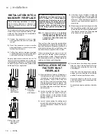
Страница 42: ...ust be installed as per the require ments of your local inspection authority Three methods of flue connection are acceptable in most areas these include 1 Positive flue connection where a large blocking plate and a short connector pipe is used 2 Direct flue connection where a smaller blocking plate and a connector pipe to the first flue liner tile is used 3 Full flue liner where a stainless steel ...

Страница 43: ...bolts and slide defector upward and out Install new defector and hand tighten bolts Ensure positive location of the defector prior to hand tightening WARNING Operation of the unit with out proper installation of smoke deflector will void warranty Smoke deflector is installed through the door opening in location shown in diagram Smoke deflector Ensure defector is seated so bolts are situated at the...

Страница 44: ...UPPORT INSTALLATION 918 676d 09 02 16 1 I1200 FACEPLATE TRIM FAN OPTIONAL BOTTOM FACEPLATE FAN SUPPORT INSTALLATION Regular Faceplate Dimensions shown with bottom faceplate fan support attached Oversize Faceplate Dimensions shown with bottom faceplate fan support attached ...

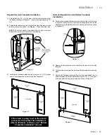
Страница 45: ...Rear View 4 Position the assembled faceplate side and top to the insert Ensure to align the draft rod into the opening of the faceplate as well as the side faceplate slots with the bolts in the mounting brackets as shown in Diagram 3 5 Measure the height between the hearth and the bottom of the side faceplate 6 Cut the bottom faceplate to the measured height using a metal cutting blade 7 Remove th...

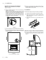
Страница 46: ...ided as shown in Diagram 6 11 Mount the completed faceplate trim assembly to the insert Ensure to align the side faceplate slots with the hex bolts in the mounting brackets and tighten to secure in place Diagram 5 Diagram 6 Shown with Optional Bottom Faceplate Regular Oversize Faceplate Trim Installation Black Trim included with Regular Oversize Faceplate or Bottom Faceplate Fan Installation 12 In...

Страница 47: ...4 self tapping screws See Diagram 9 Diagram 9 Rear Bottom View 18 Secure the bottom faceplate to the 3 sided faceplate using the 4 supplied bolts washers 19 Discard both side trims that were included with the regular oversize faceplate and replace with the new extended trims supplied with the fan support bottom faceplate Cut to desired length 20 Fit the trim assembly over the faceplate assembly Se...

Страница 48: ...eclips Thetension holdingtheclipsinplacemaybeadjustedby increasing or decreasing the offset spacing of the clips 3 Ensure that the power cord is not in contact CAUTION Label all wires prior to disconnection when servic ing controls Wiring errors can cause improper and dangerous operation WARNING Electrical Grounding Instructions This appliance is equipped with a three pronged grounding plug for yo...

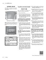
Страница 49: ... the two air tubes are installed continue on to Step 2 if not follow the instructions below Installtheairtubeintotheholesinthe side channels The notch goes on the right hand side with the air holes facing toward the door Slide the tube into the left hand side asfaraspossibleandthenbringitback into the hole on the right hand side until it locks into position If the tube will not slide in easily sim...

Страница 50: ...e difficult to start the fire As you dry out your fire brick and your masonry flue if applicable your draft will increase 10 Forthoseunitsinstalledathigherelevations or into sub standard masonry fireplaces drafting problems may occur Consult an experienced dealer or mason on methods of increasing your draft 11 Some cracking and popping noises may be experienced during the heating up process Thesen...

Страница 51: ...ate the fan system push the first switch to Man and second switch to either high or Low This will bypass the sensing deviceandallowfullcontrolofthefan Switching from Auto to Manual or High to Low may be done at any time ASH DISPOSAL During constant use ashes should be removed every few days Please take care to prevent the build up of ash around the start up air housing located inside the firebox u...

Страница 52: ... the spacer washer shown in the diagram below will allow the latch to be moved closer to the door frame causing a tighter seal Removeandreplacethenuts washerasshown GLASS CLEANING Do not attempt to clean the glass when it is hot allow the glass to cool before cleaning Do not use abrasive cleaners to clean the glass Your local retailer can supply you with special glass cleaner if plain water and a ...

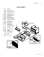
Страница 53: ... 17 846 918 Hinge Caps 2 set Gold 19 948 101 Spring Handle Large Gold 20 948 102 Spring Handle Small Gold 170 915 Fan Blower Assembly 24 910 157 P Blower Fan Motor 25 910 678 Power Cord 120 Volts 27 910 142 Fan Thermodisc 28 910 140 Fan Speed Switch HI OFF LOW 3 way 29 910 138 Switch Auto Manual 2 way 30 Grommet Strain Relief 35 074 954 Air Tube 1 Qty 1 36 033 953 Air Tube 3 4 Qty 1 38 073 955 Baf...

Страница 54: ... Trim Set Oversize Black 171 926 Trim Set Oversize Brass 171 572 Trim Set Oversize Black 171 928 Bottom Piece and Fan Support Regular 171 930 Bottom Piece and Fan Support Oversize 60 Faceplate Right Side Regular Oversize 61 Faceplate Left Side Regular Oversize 62 Faceplate Top Regular Oversize 64 Bottom 1 Piece Faceplate 65 Fan Support Not available as a replacement part ...

Страница 55: ...ion 170 960 Complete Brick Set 70 Brick Regular Full Size 1 1 4 x 4 1 2 x 9 76 Brick Partial 1 1 4 x 2 x 9 81 Brick Partial 1 1 4 x 1 1 4 x 9 84 Brick Partial 1 1 4 x 4 1 2 x 8 85 Brick Partial 1 1 4 x 4 1 4 x 8 Not available as a replacement part ...

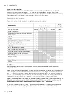
Страница 56: ...ated 3 Venting Chimney 1 Screens 1 Conditions Warranty protects against defect in manufacture or FPI factory assembled components only unless herein specified otherwise Any part s found to be defective during the warranty period as outlined above will be repaired or replaced at FPI s option through an accredited distributor dealer or pre approved and assigned agent provided that the defective part...

Страница 57: ... operator error abuse misuse use of improper fuels such as unseasoned cordwood mill ends construction lumber or debris off cuts treated or painted lumber metal or foil plastics garbage solvents cardboard coal or coal products oil based products waxed cartons compressed pre manufactured logs lack of regular maintenance and upkeep acts of God weather related problems from hurricanes tornados earthqu...

Страница 58: ...ditional terms which may be applicable to this warranty How to Obtain Warranty Service Customers should contact the authorized selling dealer to obtain warranty service In the event the authorized selling dealer is unable to provide warranty service please contact FPI by mail at the address listed below Please include a brief description of the problem and your address email and telephone contact ...

Страница 59: ...s to serve you better Warranty Registration Form or Register online immediately at the above Web Site Warranty Details Serial Number required Purchase Date required mm dd yyyy Product Details Product Model required Dealer Details Dealer Name required Dealer Address Dealer Phone Installer Date Installed mm dd yyyy Your Contact Details required Name Address Phone Email For purchases made in CANADA F...

Страница 60: ...28 I1205 28 warranty ...

Страница 61: ...I1205 29 29 notes ...

Страница 62: ...30 I1205 30 notes ...

Страница 63: ...I1205 31 31 ...

Страница 64: ...lete the following information Dealer Name Address _____________________________________ ________________________________________________________ Installer __________________________________________________ Phone _ ________________________________________________ Date Installed _____________________________________________ Serial No ________________________________________________ ...

Отзывы: