3
Step 3:
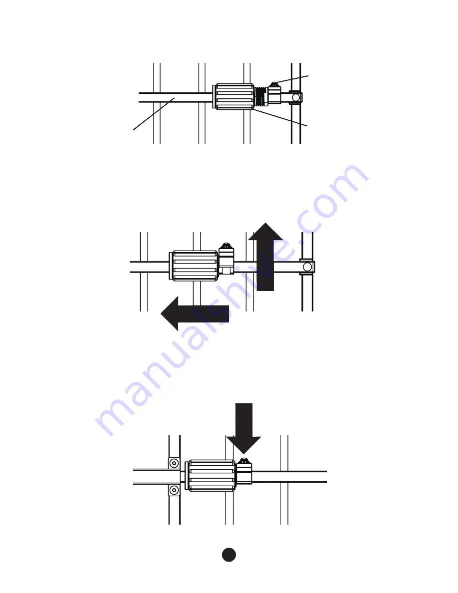
To lock the gate into position, pull up on the Locking Pin and slide the
Adjustment Device towards the center of the gate. As shown in Diagram D.
Step 4:
When the Adjustment Device can go no further, push down on the
Locking Pin. The pin will insert into one of the holes on the Horizontal Bar and
secure the Adjustment Device in place. As shown in Diagram E.
Diagram C
Diagram E
Diagram D
Locking Pin
Horizontal Bar
Turning Knob
Adjustment Device
2. SLIDE
1. LIFT
PUSH
Содержание 0724
Страница 2: ......


