24
10 DIP Switches
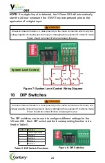
Table 5: DIP Switch Functions
Figure 8: DIP Switches
Switch # Function
1
Power output on/off
2
Not Used
3
Not Used
4
Not Used
5
Not Used
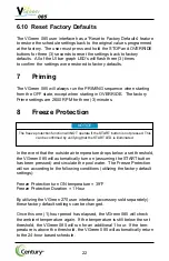
Figure 7: System Level Control Wiring Diagram
Relay 1
Relay 2
Relay 3
Relay 4
Load
Load
Load
Load
Line
Line
Line
Line
System Level Control
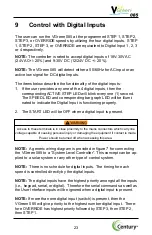
Access to these terminals is in close proximity to the mains connectors which carry line
voltage capable of causing personal injury or damaging the equipment if contact is made.
Power should be turned off when accessing this area.
The DIP switches can be used to configure different settings for the
VGreen 085. Each DIP switch and their corresponding function is de-
fined in Table 5.
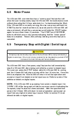
Access to these terminals is in close proximity to the mains connectors which carry line
voltage capable of causing personal injury or damaging the equipment if contact is made.
Power should be turned off when accessing this area.
NOTE:
If no digital input is detected, the VGreen 085 will automatically
start the 24 hour schedule if the START key was pressed prior to the
application of a digital input.


