background image

14

OPERATION AND ADJUSTMENT

THE PRE-LUBRICATED WALKING BELT

Your treadmill features a walking belt coated with high-

performance lubricant.

IMPORTANT: Never apply sil-

icone spray or other substances to the walking

belt or the walking platform. Such substances will

deteriorate the walking belt and cause excessive

wear.

HOW TO PLUG IN THE POWER CORD

Your treadmill, like any other type of sophisticated

electronic equipment, can be seriously damaged by

sudden voltage changes in your homeʼs power.

Voltage surges, spikes, and noise interference can

result from weather conditions or from other appliances

being turned on or off.

To decrease the possibility of

your treadmill being damaged, always use a surge

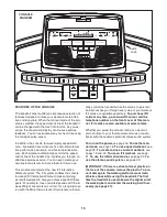
suppressor with your treadmill (see drawing 1 at

the right). To purchase a surge suppressor, see

your local REEBOK dealer or call the telephone

number on the front cover of this manual and order

part number 146148, or see your local electronics

store.

Use only a single-outlet surge suppressor that is

UL 1449 listed as a transient voltage surge sup-

pressor (TVSS). The surge suppressor must have a

UL suppressed voltage rating of 400 volts or less

and a minimum surge dissipation of 450 joules.

The surge suppressor must be electrically rated for

120 volts AC and 15 amps. There must be a moni-

toring light on the surge suppressor to indicate

whether it is functioning properly. Failure to use a

properly functioning surge suppressor could result

in damage to the control system of the treadmill. If

the control system is damaged, the walking belt

may change speed, accelerate, or stop unexpect-

edly, which may result in a fall and serious injury.

This product must be grounded.

If it should malfunc-

tion or break down, grounding provides a path of least

resistance for electric current to reduce the risk of elec-

tric shock. This product is equipped with a cord having

an equipment-grounding conductor and a grounding

plug.

Plug the power cord into a surge suppressor,

and plug the surge suppressor into an appropriate

outlet that is properly installed and grounded in

accordance with all local codes and ordinances.

IMPORTANT: The treadmill is not compatible with

GFCI-equipped outlets.

This product is for use on a nominal 120-volt circuit,

and has a grounding plug that looks like the plug illus-

trated in drawing 1 below. A temporary adapter that

looks like the adapter illustrated in drawing 2 may be

used to connect the surge suppressor to a 2-pole

receptacle as shown in drawing 2 if a properly

grounded outlet is not available.

The temporary adapter should be used only until a

properly grounded outlet (drawing 1) can be installed

by a qualified electrician.

The green-colored rigid ear, lug, or the like extending

from the adapter must be connected to a permanent

ground such as a properly grounded outlet box cover.

Whenever the adapter is used it must be held in place

by a metal screw.

Some 2-pole receptacle outlet box

covers are not grounded. Contact a qualified elec-

trician to determine if the outlet box cover is

grounded before using an adapter.

DANGER:

Improper connection

of the equipment-grounding conductor can

result in an increased risk of electric shock.

Check with a qualified electrician or service-

man if you are in doubt as to whether the

product is properly grounded. Do not modify

the plug provided with the product—if it will

not fit the outlet, have a proper outlet

installed by a qualified electrician.

1

2

Grounded Outlet Box

Grounded Outlet Box

Grounding Plug

Surge Suppressor

Surge Suppressor

Grounding Pin

Adapter

Lug

Metal Screw

Grounded Outlet

Grounding Pin

Содержание RBTL21908.0

Страница 1: ...n the space above for reference www reebokfitness com QUESTIONS If you have questions or if parts are damaged or missing DO NOT CONTACT THE STORE please contact Customer Care IMPORTANT You must note t...

Страница 2: ...WARRANTY Back Cover This drawing shows the locations of the warning decals If a decal is missing or il legible call the telephone number on the front cover of this manual and request a free replacemen...

Страница 3: ...urge suppres sor not included and plug the surge sup pressor into a grounded circuit capable of carrying 15 or more amps No other appliance should be on the same circuit Do not use an extension cord 1...

Страница 4: ...23 You must be able to safely lift 45 lbs 20 kg to raise lower or move the treadmill 22 Do not change the incline of the treadmill by placing objects under the treadmill 23 When folding or moving the...

Страница 5: ...ease see the front cover of this man ual To help us assist you note the product model number and serial number before contacting us The model number and the location of the serial number decal are sho...

Страница 6: ...ild non abrasive cleaner Assembly requires the included hex keys and your own Phillips screwdriver and adjustable wrench Use the drawings below to identify the assembly hardware The number in parenthe...

Страница 7: ...efully tip the treadmill onto its left side Partially fold the Frame 51 so the treadmill is more stable Do not fully fold the Frame until the treadmill is completely assembled Attach six Base Feet 86...

Страница 8: ...yet Be careful not to pinch the Upright Wire 76 4 7 11 8 Plate 100 83 5 With the help of a second person carefully tip the treadmill onto its right side Partially fold the Frame 51 so the treadmill i...

Страница 9: ...drawing The connectors should slide together easily and snap into place If they do not turn one connector and try again Locate the incline wire in the end of the Pulse Bar 99 Hold the Left Handrail 94...

Страница 10: ...n tighten the four 8 x 1 2 Screws 2 in the Left Handrail 94 Note The Screws are preattached Attach the Right Handrail Cover 103 to the console assembly in the same way Tighten two 1 4 x 1 2 Patch Bolt...

Страница 11: ...ONSOLE MAY BE DAM AGED WHEN THE POWER IS TURNED ON Remove the wire tie from the Upright Wire 76 Insert the excess wire into the Right Upright 100 as you set the console assembly on the Right Upright a...

Страница 12: ...so that the large barrel and the Latch Knob 81 are oriented as shown Attach the Latch Bracket 90 and Storage Latch 80 to the Base 83 with two 3 8 x 2 Bolts 6 and two 3 8 Nuts 12 Attach the upper end...

Страница 13: ...ys is used to adjust the walking belt see pages 26 and 27 To protect the floor or carpet from damage place a mat under the treadmill 15 With the help of a second person carefully lower the Uprights 77...

Страница 14: ...c tion or break down grounding provides a path of least resistance for electric current to reduce the risk of elec tric shock This product is equipped with a cord having an equipment grounding conduct...

Страница 15: ...ted pounds with the 8 week Weight Loss workout or train for a long distance run with the Marathon workout iFit workouts automati cally control the treadmill while the voice of a personal trainer coach...

Страница 16: ...r simplicity all instructions in this section refer to miles HOW TO USE THE MANUAL MODE 1 Insert the key into the console See HOW TO TURN ON THE POWER at the left 2 Select the manual mode Each time th...

Страница 17: ...remove the sheets of clear plastic from the metal contacts In addition make sure that your hands are clean To measure your heart rate stand on the foot rails and hold the metal contacts on the handra...

Страница 18: ...ng for the current segment At the end of each segment a series of tones will sound and the next segment of the profile will begin to flash If a new speed and or incline setting is programmed for the n...

Страница 19: ...vided into several one minute segments One speed setting and one in cline setting can be programmed for each seg ment To program speed and incline settings for the first segment simply adjust the spee...

Страница 20: ...ive segments The custom workout will function in the same way as a speed workout see step 3 on page 18 If desired you can redesign the workout while using it To change the speed setting or the in clin...

Страница 21: ...one of the Speed increase buttons to start the workout A moment after you press the button the treadmill will automatically ad just to the first speed and incline settings of the workout Hold the hand...

Страница 22: ...function nor mally when you plug in the power cord switch the reset off circuit breaker to the reset position and insert the key into the console However when you remove the key the displays will rema...

Страница 23: ...knob is locked in the storage position To protect the floor or carpet from damage place a mat under the treadmill Keep the treadmill out of di rect sunlight Do not leave the treadmill in the stor age...

Страница 24: ...nob Note It may be necessary to push the frame forward as you pull the latch knob to the left 2 Hold the metal frame firmly with both hands and lower it to the floor CAUTION To decrease the possibilit...

Страница 25: ...se SOLUTION a Check the reset off circuit breaker see the drawing above If the circuit breaker has tripped wait for five minutes and then press the switch to the reset position b Make sure that the po...

Страница 26: ...to the minimum level This will recalibrate the incline system If the incline does not calibrate press the Stop button and then press the Incline increase or decrease button again When the incline is c...

Страница 27: ...Plug in the power cord insert the key and run the treadmill for a few minutes Repeat until the walking belt is centered b If the walking belt slips when walked on first remove the key and UNPLUG THE P...

Страница 28: ...your goal is to strengthen your cardiovascular system you must perform aerobic exer cise which is activity that requires large amounts of oxygen for prolonged periods of time For aerobic ex ercise adj...

Страница 29: ...ail Insert 41 1 Left Foot Rail 42 1 Warning Deal 43 4 Isolator 44 2 Belt Guide 45 1 Walking Platform 46 2 Frame Spacer 47 1 Drive Roller Pulley 48 1 Magnet 49 1 Lift Frame Drive Roller Ground Wire 50...

Страница 30: ...Tray 114 1 Right Accessory Tray 115 1 Console Base 116 1 5 32 Hex Key 117 1 Small Left Pulse Sensor 118 1 Large Left Pulse Sensor 119 1 Right Small Pulse Sensor 120 1 Right Large Pulse Sensor 121 1 K...

Страница 31: ...4 18 2 43 16 46 48 45 47 44 31 30 15 20 33 55 34 15 30 54 2 17 53 33 31 34 56 20 14 13 52 51 43 2 43 2 24 49 23 44 16 18 18 19 19 19 19 41 19 19 19 19 53 40 50 78 78 116 EXPLODED DRAWING A Model No RB...

Страница 32: ...57 58 36 1 36 1 1 36 59 60 21 67 23 68 28 66 23 37 61 62 12 63 64 37 29 12 46 65 22 22 22 1 23 74 75 73 72 71 22 1 22 70 22 69 1 82 16 27 16 5 EXPLODED DRAWING B Model No RBTL21908 0 R1208A 32...

Страница 33: ...1 11 9 80 79 100 1 84 83 26 39 81 12 6 35 25 85 86 11 7 85 86 8 87 91 85 86 4 12 12 90 6 88 87 12 91 7 4 86 85 76 26 39 35 25 84 1 85 86 4 85 86 4 8 11 11 7 88 4 7 4 77 124 EXPLODED DRAWING C Model No...

Страница 34: ...34 92 93 27 2 2 95 2 1 96 97 23 3 2 11 2 94 2 2 99 2 10 2 2 98 2 102 2 11 10 3 27 92 101 103 2 2 2 23 97 1 104 110 110 EXPLODED DRAWING D Model No RBTL21908 0 R1208A...

Страница 35: ...105 1 106 1 2 2 108 2 2 115 2 2 2 2 2 2 112 107 1 121 38 38 117 118 2 2 2 38 123 23 2 109 2 2 2 2 122 120 119 1 1 2 2 114 2 2 111 1 113 89 89 EXPLODED DRAWING E Model No RBTL21908 0 R1208A 35...

Страница 36: ...e for a minimal handling charge For in home service the customer will be responsible for a minimal trip charge This warranty does not extend to any damage to a product caused by or attributable to fre...

Отзывы: