


www.redbackaudio.com.au
Redback® Proudly Made In Australia
5
Redback® A 4270/80
Four Zone Paging PA Amplifier
4.0 REAR PANEL CONNECTIONS
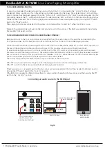
Figure 2 shows the layout of the rear panel.
Fig 2
1
100V Out (Main) Output Connections
This is the main output of the amplifier and is for connection of speakers fitted with a 100V line transformer.
Always ensure that the total load of the speakers does not exceed the rated output of the amplifier i.e. 80Ω
minimum at 100V for 125W and 40Ω minimum at 100V for 250 Watts. Otherwise either the DC or mains fuse
could blow or the fault led to activate and the amp will shut down. Always be careful to avoid short circuits and
connection to the wrong terminals.
2
100V Out (Out1 - Out4) Output Connections
These 100V line outputs are for zones which can be paged when the optional A 4488 paging microphones are
connected. Background music can be piped to these outputs via the front switches.
3
Connections for A 4488 Paging Consoles
These RJ45 ports are for connection of the optional A 4488 paging consoles.
4
Alert/Evacuation Tone Generator with Voice Over Message
Use these contacts to trigger the chime tones, the alert tone, the evacuation tone and to cancel any
of the tones once triggered. All tones & cancel function are operated by a closing contact to ground.
This could be triggered via a building fire indicator board, break glass alarm etc.
All tones are MP3 based files and are stored on the supplied Micro SD card.
(Refer to section 15.0 for more details).
5
DIP Switches
These switches provide various functions (refer to section 17.0).
6
Micro SD Card
This is used to store the MP3 files used for the Alert, Evac and Chime tones and also the Voice over messages.
(Refer to section 15.0 for more details).
7
Inputs 1-3
These inputs can be either a balanced XLR input with sensitivities of 500mV or dual RCA line inputs with a 1V
input sensitivity. The line input dual RCA connectors are internally mixed to produce a mono input signal.
8
Tape Out
Dual RCA’s provided for recording purposes. This is a line level output.
9
Optional Plugin
This connection is to be used when the optional A 4373 Digital Volume Board if fitted inside the amplifer. This
provides remote volume when used in conjunction with a 1K potentiometer wired to these terminals.
10
24VDC IN
Battery Backup: Provision has been provided to run the amplifier from a suitably rated 24V battery system in the
event of a mains failure. Using appropriately rated cable, connect the battery to the “24V DC In” terminals.
Observe correct polarity when connecting. (see Fig 5 for more details)
11
DC Resettable fuses
This fuse protect the internal power supply. If the fuse is tripped it is easily reset by pressing the small button on
the fuse.
12
240V AC power socket (Australian standard)
Connects to 240V AC mains power with the included IEC lead. The internal fuse is an M205 5Amp for the
A 4270 125 Watt amplifier and an M205 7.5Amp for the A 4280 250 Watt amplifier.
7
8
1
2
9
10
11
3
4
5
6
12
240V AC @ 50Hz
RISK OF ELECTRIC SHOCK
OPEN BY QUALIFIED
PERSONNEL ONLY
!
CAUTION
Tape Out
Line 1
Mic 3
Mic 2
Mic 1
1
2
3
1 • Shield
2 • Hot
3 • Cold
MIc XLR
wiring
Configuration
Line 2
Line 3
L
R
L
R
L
R
Output
125W
Fuse
5 Amp
7.5 Amp
250W
AC Fuse (M 205)
DC Fuse
Output
125W
10 Amp
20 Amp
250W
Resettable
DC Fuse
L
R
Optional
Plugin
- +
+ _
24V
DC IN
Made in Australia by
Altronic Distributors Pty Ltd
www.redbackaudio.com.au
CH1
CO
M
CAN
EV
100V OUT
(MAIN)
- +
+ _
AL
CH2
OUT4
(100V)
OUT3
(100V)
OUT2
(100V)
OUT1
(100V)
Evac
Volume
V/Over
Volume
Chime
Volume
DIP
Switches
To Paging
Console 1
To Paging
Console 2
(16GB
Maximum)
Micro SD Card
Output
Triggers
Levels
+ _
+ _
+ _
+ _
1 2
3
4
2
1
3
2
1
3
2
1
3


