


To set up and enable Sensor Sync Mode, follow the instructions below:
1. Connect the genlock device to the camera:
DSMC2 Base Expander, DSMC2 V-Lock I/O Expander, DSMC2 Jetpack Expander, or DSMC2 Jetpack-
SDI Expander
: Connect the
SYNC
port (00B) on the expander to the device (green BNC) using a 3BNC-to-00
LEMO Sync Cable.
DSMC2 REDVOLT Expander
: Connect the
GENLOCK
port on the expander to the device using a 75 ohm
BNC cable.
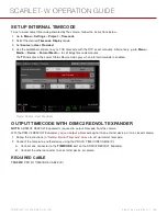
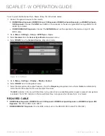
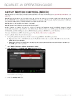
2. Go to
Menu
>
Settings
>
Setup
>
GPIO/Sync
>
Sync
.
3. Select
Genlock
from the
Sensor Sync Mode
drop-down menu.
4. Select
BRAIN
from the
Genlock Source
drop-down menu.
Figure: Sync Settings
5. Go to
Menu
>
Settings
>
Display
>
Monitor Control
.
6. Select
HDSDI
from the drop-down menu.
7. Select the desired monitor output frequency from the
Frequency
drop-down menu. Select
Auto
to automatically
match the HD-SDI output to the current project time base.
The
GEN
indicator in the Lower Status Row turns green when a compatible genlock signal is present and genlock
is enabled. The SYNC indicator in the Lower Status Row turns green when Sensor Sync is achieved.
REQUIRED CABLE
DSMC2 Base Expander, DSMC2 V-Lock I/O Expander, DSMC2 Jetpack Expander, or DSMC2 Jetpack-SDI
Expander
: 790-0154, 3BNC-to-00 LEMO
DSMC2 REDVOLT Expander
: 75 ohm BNC cable (such as the RED HD-SDI Cable, P/N 790-0341)
C O PYR I G HT © 2 0 1 6 R ED.C O M , I NC
9 5 5 - 0 1 3 3 _V 6 .3 , R EV - H
|
1 6 8
SCARLET-W OPERATION GUIDE
Содержание SCARLET-W
Страница 1: ...SCARLET W RED DRAGON MONOCHROME V6 3 RED COM SCARLET W OPERATION GUIDE ...
Страница 201: ...FRONT VIEW Figure SCARLET W Front View COPYRIGHT 2016 RED COM INC 955 0133_V6 3 REV H 201 SCARLET W OPERATION GUIDE ...
Страница 202: ...BACK VIEW Figure SCARLET W Back View COPYRIGHT 2016 RED COM INC 955 0133_V6 3 REV H 202 SCARLET W OPERATION GUIDE ...