background image

14

8. Machine Assembly - Cont.

90º

90º

Fence Alignment 1

Adjustment can be made to the fence (Fig. 8.6, A) in 
relation to being parallel to the blade. This is done by 
slackening the four wing nuts on the fence rail (Fig. 8.6, B) 
and adjusting the rails position until the fence is parallel 
to the blade.

Note: 

This adjustment must be made with the fence in a 
clamped position

Fig. 8.6

A

B

Fence Alignment 2

Check that the fence (Fig. 8.7, A) is 90º to the table 
(Fig. 8.7, B) using a suitable square, there is no need for 
adjustment as this area is factory set. However if settings 
have slipped during transit slight adjustment may be 
needed. The best way to adjust this is by adding extra 
washers or shims between the fence rail (Fig. 8.7, D) and 
the underside of the table where required. 

Tip: 

When an accurate cut is crucial it is good practice to 
check all settings before machining the workpiece 
and make a test cut with some scrap material.

Fig. 8.7

A

B

D

C

i

Kg

i

Kg

Fitting the Rip Fence

1.   Slide the rip fence (Fig. 8.5, A) assembly onto the fence 

rail (Fig. 8.5, B) ensuring that the retaining plate at the 
end of the rip fence is located under the rear edge of  
the table. 

2.   Pull down the locking lever (Fig. 8.5, C) to secure  

the position.

Checking the Drive Belt Tension

The tension of the drive belt must also be checked before 
operation of the machine. Please see the maintenance 
section of the manual for further details.

Tip: 

When locking the rip fence it is advisable to place 
downward pressure on the top of the fence with one 
hand. This ensures that the fence registers correctly in 
the fence rail.

i

Kg

Fig. 8.5

A

B

C

Содержание BS10

Страница 1: ...g woodworking equipment Always read the instructions provided before using woodworking equipment i Kg Version 3 1 February 2014 To register this product please visit www recordpower info It is important to register your product as soon as possible in order to receive efficient after sales support and be entitled to the full 5 year guarantee Your statutory rights are not affected Please see back co...

Страница 2: ...ional Health Safety Guidance for Bandsaws 4 Record Power Guarantee 5 Getting to Know the Bandsaw 6 Specifications 7 Assembly of the Optional Leg Stand 8 Machine Assembly 9 Machine Setting 10 Bandsaw Blade Set Up 11 Electrical Connection Wiring Diagram 12 Operation Bandsawing Practice 13 Dust Extraction 14 Maintenance 15 Parts List Diagrams EU Declaration of Conformity ...

Страница 3: ... to use the machine Indicates an instruction that requires particular attention Wear protective eyewear Use respiratory protective equipment Use suitable protective footwear Use hearing protection Use protective work gloves Indicates a risk of severe personal injury or damage to the machine Indicates a risk of severe personal injury from electrical shock Risk of personal injury from lifting of hea...

Страница 4: ... area Some machines have optional wheel kits available to allow them to be manoeuvred around the workshop as required Care should be taken to install these according to the instructions provided Due to the nature of the design of some machines the centre of gravity will be high making them unstable when moved Extreme care should be taken when moving any machine If transportation of the machine is ...

Страница 5: ...oss section of 2 5 mm and limited to a maximum length of 3 metres Extension cables should be routed away from the direct working area to prevent a trip hazard 19 Guard against electric shock Avoid body contact with earthed or grounded surfaces such as pipes and radiators There is an increased risk of electric shock if your body is earthed or grounded 20 Always work within the machine s intended ca...

Страница 6: ...e from their website www hse gov uk 3 Additional Health Safety Guidance for Bandsaws guards in place 27 Maintain your machine with care This manual gives clear instructions on installation set up and operation of the machine and also details any routine and preventative maintenance that should be performed periodically by the user Remember always to switch off and unplug the machine from the power...

Страница 7: ... been purchased from a retailer the 5 year guarantee is transferable and begins on the date of the first purchase of the Product and in the event of a claim under this guarantee proof of the original purchase date will be required to validate the warranty period 2 Claims Procedure 2 1 In the first instance please contact the Authorised Dealer who supplied the Product to you In our experience many ...

Страница 8: ...without stand H887 x W528 x D387 mm Size with stand H1565 x W630 x D458 mm Sound power level 85 dBA Sound pressure level 85 dBA 5 Getting to Know the Bandsaw 6 Specifications A Blade tensioning knob B Rise fall knob C Blade D Upper blade guides E Mitre fence F Rip fence G Rip fence rail H Table I Optional leg stand J Tracking knob K Tracking knob lock L Motor rating plate M Table tilting handle N ...

Страница 9: ...ong fixing bolts and nuts x 4 G Short fixing bolts nuts and washers x 16 H Washers x 40 CAUTION The machine is heavy Additional help or a suitable lifting device or support will be required for lifting the machine onto the stand Tools Required For Assembly Maintenance 3 mm hex wrench included with the machine 5 mm hex wrench not supplied 10 13 mm combination wrench included with the machine i Kg i...

Страница 10: ...ame Fig 7 1 2 The locating holes a third of the way down each leg are for securing the long mid brace supports B Fix the long mid brace supports to the frame using the short nuts bolts and washers G Fig 7 2 3 Finally fit the two short mid brace support C to the shorter sides of the stand Fig 7 3 Note When assembling the legstand do not fully tighten the nuts and bolts until the assembly is complet...

Страница 11: ...itting the Bandsaw to the Stand 1 Lift the bandsaw over the stand and place the long fixing bolts F through the four location holes in the bandsaw base Fig 7 5 2 Secure the bandsaw to the stand with the remaining washers and nuts Fig 7 6 F CAUTION The machine is heavy Additional help or a suitable lifting device or support will be required for lifting the machine onto the stand i Kg i Kg D E Fig 7...

Страница 12: ...chine the following components are included for the initial assembly G H J K I A BS10 Bandsaw B Table C Fence D Fence rail E Mitre fence F Push stick G M6 x 15 mm hex head screw H Serrated washers x 4 I Wing bolts x 4 J Washers x 4 K 3 mm Hex key L M6 x 30 mm hex bolt M M6 nut N 10 and 13 mm open ended wrench O M6 nut and push stick holder B D F C E N O A L M ...

Страница 13: ...le in the underside of the table Fig 8 2 B This acts as the table stop at 90ºand will need to be adjusted once the table is fitted described later in this section Position the table on the trunnion of the machine aligning the holes in the trunnion with the fixing holes in the underside of the table Fig 8 3 Secure with the 4 M6 x 15 mm hex head screws and 4 serrated washers supplied Fitting the Fen...

Страница 14: ...e fence rail Fig 8 7 D and the underside of the table where required Tip When an accurate cut is crucial it is good practice to check all settings before machining the workpiece and make a test cut with some scrap material Fig 8 7 A B D C i Kg i Kg Fitting the Rip Fence 1 Slide the rip fence Fig 8 5 A assembly onto the fence rail Fig 8 5 B ensuring that the retaining plate at the end of the rip fe...

Страница 15: ... to give an indication of adjustment required 2 Adjust the table until it is 90º to the blade If the table stop screw Fig 9 3 G position is too high it may be necessary to wind this down out of the way so 90º can be achieved 3 Once the table is at 90º to the blade tighten the lock handle to secure the table position 4 Now set the table stop screw Fig 9 3 G the table stop screw should be adjusted t...

Страница 16: ...des to 150 mm above the table making sure the bandsaw is turned off Push the blade sideways with a reasonable amount of pressure using a push stick A correctly tensioned blade should not move more than 4 mm sideways Fig 9 4 A If the blade is over tightened as in Fig 9 4 B the blade could be damaged However perhaps the most tried and tested way of blade tensioning is simply If the bandsaw is cuttin...

Страница 17: ...ve to the front of the bandwheel The blade should run as close to the centre of the bandwheel as possible Fig 9 6 After the blade is tracked in the desired position on the bandwheel rotate the wheel several more times by hand without any further adjustment ensuring that the blade remains in the same position Once this has been achieved lock the tracking knob with the winged nut Fig 9 5 A Note It t...

Страница 18: ... assembly and move the assembly until the blade guides Fig 10 5 B are just behind the gullets of the blade Fig 10 2 Set the blade guides relative to the blade by loosening the blade guide knob Fig 10 5 C and moving the blade guides to be as close as possible to the blade without touching it Fig 10 3 Set the rear thrust guide by loosening the rear thrust guide knob Fig 10 5 D and positioning the re...

Страница 19: ...e UK always ensure that it is fitted with a fuse conforming to BS1362 appropriate to the rating of the machine If replacing the original fuse always fit a fuse of equivalent rating to the original Never fit a fuse of a higher rating than the original Never modify the fuse or fuse holder to accept fuses of a different type or size Where the current rating of the machine exceeds 13 A at 230 V or if ...

Страница 20: ...ur country Restarting In the Event of a Blockage or if the Machine Stalls If the bandsaw stalls due to the blade becoming trapped in the work piece switch it off immediately by pressing the emergency stop button and wait for the machine to come to a complete stop before proceeding further If the blade is trapped within the work piece it may be necessary to prize the work piece apart slightly using...

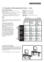
Страница 21: ...ial to be sawn it is essential that the saw blade is allowed to cut freely by not applying too much pressure The need for excessive pressure is likely to be a result of the incorrect blade selection or a worn blade and will result in inaccurate cutting and possibly blade breakage Blade Selection Width When cutting shapes the width of the blade limits the minimum radius that can be cut If the blade...

Страница 22: ...lades please contact Record Power Customer Services in your country who will advise you of your nearest retailer or alternatively a mail order supplier BB67121406 1 4 x 6 TPI Bandsaw Blade BB67123804 3 8 x 4 TPI Bandsaw Blade BB67123806 1 2 x 4 TPI Bandsaw Blade BB67121206 1 2 x 6 TPI Bandsaw Blade BB6712 3PACK 1 4 x 6 TPI 3 8 x 6 TPI and 5 8 x 6 TPI Bandsaw Blades i Application Narrow Blade Wide ...

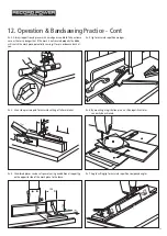
Страница 23: ...causing it to spin or bounce back at you Ex 3 Use a side pressure pad for accurate cutting of taller material Ex 4 Chamfered pieces can be cut squarely using an additional support jig on the opposite side of the work piece to the fence Ex 5 Jig for accurate repetitive wedges Ex 6 By mounting a registration pin on a slide repetitive circles can easily be achieved Ex 7 Angle cutting jig for accurate...

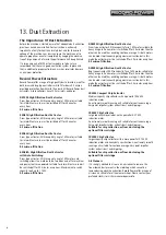
Страница 24: ...very hour Maximum auto switch capacity tools up to 1 1 kW 0 5 micron filtration DX4000 High Filtration Dust Extractor Drum type extractor 80 litre capacity Twin 1 kW motor suitable for heavy usage ie if one motor is switched off for 20 minutes then the other can be used thus enabling continuous usage Or both motors can be used simultaneously giving maximum suction but in this mode the extractor mu...

Страница 25: ...iversals Intermittent usage Planer Thicknessers Spindle Moulders Universals Heavy usage Dust Extraction System Intermittent usage 3 Recommended 3 Recommended 3 Recommended 3 Recommended 3 Recommended 3 Recommended 3 Recommended 3 Recommended 3 Recommended 3 Recommended 3 Recommended 3 Recommended 3 Recommended 3 Recommended 3 Recommended 3 Recommended 3 Recommended 3 Recommended 3 Can be used 3 Ca...

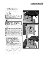
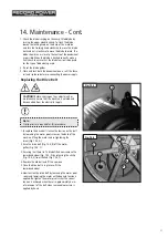
Страница 26: ...the blade passes through the table Ensuring that the blade is fully in place on the bandwheel re apply tension using the tensioning knob Adjust the blade tension to suit the new blade CAUTION Before carrying out any adjustments or maintenance ensure that the machine is isolated and disconnected from the electricity supply Replacing the Bandsaw Blade HAZARD Take great care when unpacking the bandsa...

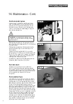
Страница 27: ...ack of the machine lifting the motor and re tightening the screw Fig 14 3 A 2 Ease the drive belt Fig 14 4 B off the motor pulley Fig 14 4 C 3 Ensuring that there isn t a blade fitted now remove the lower bandwheel Fig 14 4 D by releasing the circlip Fig 14 4 E from the hub Fig 14 4 F 4 Remove the old belt and fit the new one 5 Once the drive belt is in place re fit the lower bandwheel 6 Now tensi...

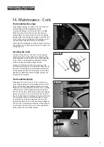
Страница 28: ...ual The Table Insert The table insert on a bandsaw is a consumable item Fig 14 7 A and will therefore need replacing periodically This procedure should be carried out with the bandsaw blade removed To replace the table insert simply push the old insert out from underneath the table and fit the new one into position The Bandwheel Tyres The bandwheels on this machine have rubber tyres fitted to the ...

Страница 29: ... particles then wipe clean with white spirit ensuring that any resin build up is dispersed and removed Once the table has been thoroughly cleaned it can now be treated with CWA195 silicone spray or wax If these guidelines are followed the timber will glide smoothly and accurately across the table The Bandwheel Brush The purpose of this brush Fig 14 10 A is to remove any excess sawdust and resin fr...

Страница 30: ...re Neck Bolt 1 47 DJ31703112 Gear Shaft 1 48 DJ31703113 Gear 1 49 DJ250A02002 Lower Blade Trunnion 1 No Part Number Part Name Quantity No Part Number Part Name Quantity 50 GB96 85 6 Washer 1 51 DJ315B03025 Guide wheel 3 52 DJ315B03027 Nut 2 53 DJ315B03025 Roller 3 54 DJ315B03023 Shaft 1 55 GB T276 94 625 2Z Bearing 3 56 31504018 Idler Wheel Shaft 3 57 DJ250A04017 Saw Blade Guard 1 58 DJ25002005 Ta...

Страница 31: ...GB93 87 14 Spring Washer 1 101 DJ250A04006 Bearing Bolt lower 1 102 GB93 87 6 Spring Washer 4 103 DJ25005003 1 Motor Mounting Plate 1 104 YYL7114 Motor 1 105 DJ250A05006 Motor Cord 1 106 DJ250A05005 Power Cord 1 107 GB6172 86 M6 Hex Head Thin Nut 2 108 GB5783 86 M6 x 20 Hex Head Bolt 4 109 31505010A Cable gland 2 110 GB70 1 M5 x 10 Screw 2 ...

Страница 32: ...32 15 Parts list and Diagrams Cont ...

Страница 33: ...33 15 Parts list and Diagrams Cont ...

Страница 34: ...2 EC LOW VOLTAGE DIRECTIVE 2006 95 EC ELECTROMAGNETIC 2004 108 EC COMPATIBILITY DIRECTIVE EN 55014 1 2006 EN 61000 3 2 2006 EN 61000 3 3 1995 A1 A2 EN 55014 2 1997 A1 and conforms to the machinery example for which the EC Type Examination Certificate No AE 5014 73510001 BM50172180 0001 has been issued by TÜV Rheinland LGA Product GmbH at Tillystrasse 2 90431 Nürnberg and complies with the relevant...

Страница 35: ...35 ...

Страница 36: ...cordpower co uk Eire Record Power Ltd Centenary House 11 Midland Way Barlborough Links Chesterfield Derbyshire S43 4XA Tel 01246 571 020 Fax 01246 571 030 www recordpower co uk Australia Tools 4 Industry Po Box 3844 Parramatta 2124 Tel 1300 124 422 Fax 1800 262 725 www recordpower com au New Zealand Tools 4 Industry Po Box 276079 Manukau City 2241 Tel 0800 142 326 Fax 09 2717 237 www recordpower c...

Отзывы: