background image

28

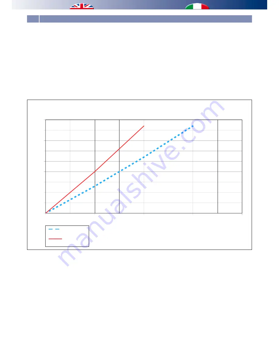
Le due curve rappresentate nel diagramma sottostante indicano 

le perdite di carico sulle batterie ad acqua di pretrattamento e 

postrattamento dell’aria nel deumidificatore. Il deumidificatore 

è predisposto con attacchi esterni separati per le batterie di 

pretrattamento e postrattamento. 

È possibile quindi alimentare le batterie separatamente con 

due linee di adduzione indipendenti o  collegarle in parallelo 

in prossimità del deumidificatore. 

La particolare configurazione geometrica  ripartisce 

automaticamente la portata sulle due batterie in ragione di 

3/5 su quella di pretrattamento

 ed 

2/5 sul postrattamento 

qualora l’alimentazione sia in parallelo sulle due batterie.

0

2

4

6

8

5

10

15

20

25

30

35

40

45

Pressure Loss of Pre- and Post-treatment Exchanger

Perdite di carico scambiatori di Pre e Post trattamento

Flow [liters/minute]

Portata [litri/minuto]

Pre-treatment 

Post-treatment

Pre trattamento

Post trattamento

Pe

rformance (kP

a)

Prevalenza [kPa]

The two curves represented in the diagram below indicate the 

pressure drop on the battery to the water of pre-treatment and 

post-treatment of the air in the dehumidifier. The dehumidifier 

is fitted with separate external attacks for pre-treatment and 

post-treatment coils. It is possible, therefore, to feed the batteries 

separately with two independent lines of adduction or connected 

in parallel near the dehumidifier. The particular geometric 

configuration automatically shares the flow on the two batteries 

at a rate of 

3/5 on that of the pre-treatment and 2/5 on that of 

post-treatment

 whenever the feed is in parallel on the two coils.

5.7 PRESSURE LOSS OF HTDRAULIC SYSTEM / PERDITA DI CARICO DEL CIRCUITO IDRAULICO

Содержание RNW 600 CS

Страница 1: ...Airhandlingunit Unità trattamento aria RNW 600 CS Dehumidifierhorizontalceilingmounted Deumidificatore orizzontale a soffitto INSTRUCTIONSFORINSTALLATIONANDUSE ISTRUZIONI PER L INSTALLAZIONE E USO ...

Страница 2: ......

Страница 3: ...o draw up the general diagram of the system and the electrical connections outside the equipment The manufacturer s technical office can be contacted on the numbers shown on the back of this manual for queries or special technical requests CAUTION Installation and maintenance must only be carried out by qualified personnel The hydraulic and electrical systems and the places where theequipmentistob...

Страница 4: ...mento e di apportare tutte le modifi che che riterrà utili o necessarie senza obbligo di preavviso In accordance with the provisions of the following European directives 2002 95 EC 2002 96 EC2003 108 EC regardingreducing the use of hazardous substances in electrical andelectronicequipment inadditiontowaste disposal The crossed out rubbish bin symbol shown on the equipment indicates that at the end...

Страница 5: ...7 4 1 Use Uso 17 4 2 Ordinary maintenance cleaning the filter Manutenzione ordinaria pulizia filtro 18 4 3 Extraordinary maintenance removing the fan Manutenzione straordinaria rimozione ventilatore 19 4 4 Visual signals Segnalazioni visive 21 4 5 Faults Guasti 21 5 TECHNICAL DATA AND PERFORMANCE DATI TECNICI E PRESTAZIONI 22 5 1 Safety controls Controlli di sicurezza 23 5 2 Components Componenti ...

Страница 6: ...entualericiclaggio alleaziende preposte allo scopo e ridurne così l impatto ambientale The unit packaging must be removed with care ensuring thatthemachineisnotdamaged Thematerialswhichmakeupthe packaging are different wood cardboard nylon etc Store them separately and deliver them for disposal or where appropriate recycling to the relevant companies thus reducing the environmental impact TESTING ...

Страница 7: ...t cooling systems incorporated in building structures must work taking care to keep the surface temperature higher than the dew point 1 DESCRIPTION OF THE EQUIPMENT DESCRIZIONE APPARECCHIATURA Table A Machine Components Tabella A Componenti apparecchiatura Rif Descriptions Descrizione A Pre treat water outlet 1 2 F Uscita acqua pre trattam 1 2 F B Post treat water outlet 1 2 F Uscita acqua post tr...

Страница 8: ...i A Pre treat water outlet 1 2 F with shut off valve to adjust flow rate A Uscita acqua pre trattam 1 2 F con valvola di intercettazione B Post treat water outlet 1 2 F with shut off valve to adjust flow rate B Uscita acqua post trattam 1 2 F con valvola di intercettazione C Pre treat water inlet 1 2 F with flow rate adjustment lockshield valve C Ingresso acqua pre trattam 1 2 F con detentore di r...

Страница 9: ...9 2 1 POSITIONING AND FIXING TO THE CEILING POSIZIONAMENTO E FISSAGGIO A SOFFITTO MAX 95 MAX 30 C Duct work Canalizzazione Positioning indications Indicazioni di posizionamento OK ...

Страница 10: ...0 c m m i n 2 c m m i n 4 0 c m No constraint nessun vincolo Fixing to ceiling Fissaggio a soffitto Minimum space allowanceses Distanze minime di rispetto 1 446 632 mm ø8mm 2 3 Washer Rondella Rubber mounts Gommino antivibrante ...

Страница 11: ...11 X X min 30 cm min 10 cm min 40 cm Trap door Botola d ispezione ...

Страница 12: ...t is advisable to check that not only the connections but also the machine hydraulic circuit are watertight as these could be damaged during transportation or on site during installation on this topic the manufacturer will only be responsible for factory defects on the dehumidifier and under no circumstances accepts responsibility for indirect damage The condensation drain and the inlet and outlet...

Страница 13: ...pra citati in caso contrario la garanzia viene a decadere immediatamente e ci sono rischi elettrici per le persone e il prodotto Thedehumidifiermustbeconnectedtoadisconnected earthed power socket The electrical system must be protected against overloads short circuits and direct and indirect contacts and comply with the laws and regulations in force in the country of use Electrical interventions m...

Страница 14: ...inals with 3x1 5mm cable phase F neutral N earth CHOOSING THE FAN SPEED The machine is normally supplied with the connection on the MIN minimum speed white wire red wire which guarantees 500 m h with head of approximately 140 Pa The other speeds can be obtained using the blue or black wires together with the common wire white wire as shown in Table E below Table E Fan speed variation Wires Air Flo...

Страница 15: ...ati in fabbrica ed etichettati con la scritta UMIDOSTATO se si dispone di un dispositivo di consenso remoto rimuovere tale ponte e procedere al suo collegamento secondo quanto indicato nello schema FORCING THE UNIT IN VENTILATION MODE ONLY Two terminals are available on the dehumidifier circuit board which allow the unit to be operated in ventilation mode only The closure of the ventilation consen...

Страница 16: ... Taria in aspirazione Valore di progetto Per raggiungere tale obbiettivo agire sulla portata dell acqua variando l apertura della valvola dell acqua refrigerata The dehumidifier must be tested together with the panel system in summer operating mode the main check to be performed is in relation to the variable capacity of the cooling water based on the desired operating conditions see Table I In th...

Страница 17: ...ble to use the ventilation mode only using the special consent see chapter 3 Electrical connections In winter operating mode this condition may be combined with the circulation of hot water allowing the machine to heat the air in this case it is not possible to dehumidify and in any case a thermostat excludes the compressor if the pre treatment water exceeds 30 C If the room temperature is fairly ...

Страница 18: ...ilter may be removed from any of the four sides by remov ing the corresponding guide Attenzione Il filtro può essere ri mosso da qualunque dei quattro lati rimuovendo la guida corri spondente 4 2 ORDINARY MAINTENANCE CLEANING THE FILTER MANUTENZIONE ORDINARIA PULIZIA FILTRO ...

Страница 19: ...19 1 3 Loosen the screw using a 10 mm wrench Allentare la vite con chiave da 10 mm 2 OFF Spento 4 3 EXTRAORDINARY MAINTENANCE REMOVING THE FAN MANUTENZIONE STRAORDINARIA RIMOZIONE VENTILATORE ...

Страница 20: ...20 1 2 3 OFF Spento Loosen the screw using a 10 mm wrench Allentare la vite con chiave da 10 mm POSIZIONAMENTO E FISSAGGIO A SOFFITTO POSITIONING AND FIXING TO THE CEILING ...

Страница 21: ...pen Interruttore di linea aperto Close the line switch Chiudere l interruttore di linea Remote consent open Consenso remoto aperto Close the consent see chapter 3 Electrical Connections Chiudere il consenso vedere cap 3 Collega menti elettrici Faulty circuit board Scheda elettronica difettosa Replace the circuit board Sostituire la scheda elettronica The fan starts up but the compressor does not I...

Страница 22: ...trica nominale W 900 Nominal air flow rate Portata aria nominale m3 h 600 Maximum head Speed 1 Prevalenza massima Vel 1 Pa 140 Average head Speed 2 Prevalenza media Vel 2 Pa 170 Minimum head Speed 3 Prevalenza minima Vel 3 Pa 200 Refrigerant R407c Refrigerante R407c gr 700 Overall machine dimensions Ingombri della macchina Height Altezza mm 349 Width Larghezza mm 690 Depth Profondità mm 718 Weight...

Страница 23: ...e e guasti chiude il contatto di un relè i cui terminali sono disponibili ai morsetti 4 5 contatto pulito max 8A Compressor An air tight typology with a bipolar asynchronous mono phase motor coupled with a rotary compressor of the latest generation Temperature sensor A PTC sensor is installed upstream from the batteries In order to detect the intake air temperature Circuit board fuse 250V 8 A Allt...

Страница 24: ...a dB Dehumidification Deumidificazione Ventilation Ventilazione Speed 1 Velocità 1 Speed 2 Velocità 2 Speed 3 Velocità 3 Speed 1 Velocità 1 Speed 2 Velocità 2 Speed 3 Velocità 3 100 125 58 60 8 62 3 66 1 70 8 75 4 54 8 59 2 61 3 65 5 70 9 75 4 125 55 4 61 9 71 7 55 5 61 5 71 5 160 53 7 59 68 9 52 4 59 1 69 1 200 250 55 3 58 8 58 9 62 1 67 7 70 4 52 2 57 2 57 7 61 5 67 9 70 6 250 52 2 55 8 64 5 51 ...

Страница 25: ...ggiarsi È importante fare in modo che le unità operino nei limiti riportati Al di fuori di tali limiti non sono garantiti né il normale funzionamento né tantomeno l affidabilità e l integrità delle unità per applicazioni particolari contattare l ufficio tecnico del Costruttore Thegraphsshownbelowdescribetheoperatingrangeoftheunit The maximum permitted temperature of the water for operation in dehu...

Страница 26: ... 30 1 50 51 8 12 3 6 2 4 2 7 0 80 1 28 44 1 15 3 6 2 4 2 1 0 10 1 13 39 8 65 7 3 6 2 4 4 0 90 2 45 84 6 12 3 6 2 4 2 9 0 50 1 78 61 4 15 3 6 2 4 2 3 0 10 1 49 51 5 ThedatareportedinTable I refertoequipmentdehumidification conditions of operation with emission of neutral air or of sensible heat levels Feeding in parallel the pre treatment and post treatment coils with a flow rate of 3 6 l min and 2...

Страница 27: ...t Coil Portata acqua sulla batteria di postrattamento Sensitive Power Potenza resa sensibile C C l min l min KW 26 55 7 1 1 0 7 1 80 3 6 2 4 1 20 15 2 4 1 6 1 60 3 6 2 4 1 70 65 7 1 2 0 8 1 50 3 6 2 4 1 90 15 2 9 1 9 1 40 3 6 2 4 1 60 24 55 7 0 7 0 5 1 20 3 6 2 4 0 80 15 1 2 0 8 0 90 3 6 2 4 1 40 65 7 0 8 0 5 1 30 3 6 2 4 1 40 15 1 8 1 2 1 10 3 6 2 4 1 30 Table M Winter mode Tabella M Caso inverna...

Страница 28: ...f Pre and Post treatment Exchanger Perdite di carico scambiatori di Pre e Post trattamento Flow liters minute Portata litri minuto Pre treatment Post treatment Pre trattamento Post trattamento Performance kPa Prevalenza kPa The two curves represented in the diagram below indicate the pressure drop on the battery to the water of pre treatment and post treatment of the air in the dehumidifier The de...

Страница 29: ... 300 400 500 600 700 800 900 1000 Ventilator RNW 600CS characteristics curve Curve caratteristiche ventilatore RNW 600CS Flow m3 h Portata m3 h Speed 1 MIN Speed 2 MED Speed 3 MAX vel 1 MIN vel 2 MED vel 3 MAX Performance Pa Prevalenza utile Pa The figure below shows the curves of the prevalence available to the ventilator of the apparatus The ductwork of the dehumidifier must be sized according t...

Страница 30: ...30 NOTES NOTE ...

Страница 31: ......

Страница 32: ...9100074 06 05 2014 ...

Отзывы: