DCN: 141-01435-01 8/30/06
11
Thermostat Network Control
The TU16 thermostat uses the UPB communications protocol, with extensions, to send and receive
network messages. For the complete UPB thermostat protocol, please refer to the RCS UPB Thermostat
Protocol Manual, document number 150-00205.
The TU16 has two UPB operation Modes, Link and Message. Link mode is a simple table of UPB Link
addresses mapped to thermostat modes or setpoints. Message Mode is a more robust protocol of
commands and messages designed for thermostats.
Link Mode Operation
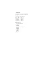
UPB supports 250 Links with IDs from 1 to 250. The thermostat Link Mode uses Link ID’s from 200 to 210.
These Link IDs are mapped to the following thermostat modes or setpoints:
Message Mode Operation
The following thermostat commands and data are typical of what can be sent and received via the UPB
Message Mode communications protocol.
UPB Setup
Network ID, Unit ID, and Link Mode Base Address
Password
Network, Room and Device Names
Thermostat Data and Control
Request temperature
Request Heat Setpoint
Request Cool Setpoint
Request System Mode (Off, Heat, Cool, Auto)
Request Fan Mode (Manual Fan Auto/Off)
Request System Operating State (Off, Heating, Cooling, Fan On/Off)
Request System Relay State (individual relay output states)
Set Heat Setpoint
Set Cool Setpoint
Set System Mode (Off, Heat, Cool and Auto)
Set Fan Mode (Auto (manual Off), On (manual On)
Set Setback Mode
Thermostat Setup
C/F degree mode
Minimum Run Time
Minimum Off Time
Autosend Mode
Test Mode
Inhibit Link Mode
Display Lockout
ID
ACTIVATE
DEACTIVATE
200
Heat Mode
Off Mode
201
Cool Mode
Auto Mode
202
Set 65F, 16C
Set 68F, 17C
203
Set 70F, 18C
Set 71F, 19C
204
Set 72F, 20C
Set 73F, 21C
205
Set 74F, 22C
Set 75F, 23C
206
Set 76F, 24C
Set 77F, 25C
207
Set 78F, 26C
Set 79F, 27C
208
Set 80F, 28C
Set 81F, 29C
209
Set 82F, 30C
Set 83F, 31C
210
Set 84F, 32C
Set 85F, 33C


