RC-512 EN-1
5
MouNtiNg iNstRuCtioNs
AssEMBly
The necessary hole cut for the installation should have a
diameter of 204 mm ±5mm. The installation depth should
amount to at least 100 mm.
1. Remove the mounting ring of the loudspeaker by relea-
sing the spring wires at both sides of the speaker.
2. Insert the ring into the mounting hole and fix it by first
loosening the thumb screw, slipping down the mounting
bracket and then fix the thumb screw again.
3. To connect the wires, it might be helpful to reconnect the
spring wires on one side of the fire dome.
4. Open the touch fastener of the loudspeaker and connect
the cables.
5. Connect the wires according to the connection dia-
grams.
6. Bring the clamps back into the bag and close the touch
fastener. Take care to close the touch fastener reliable,
especially at the cable exit!
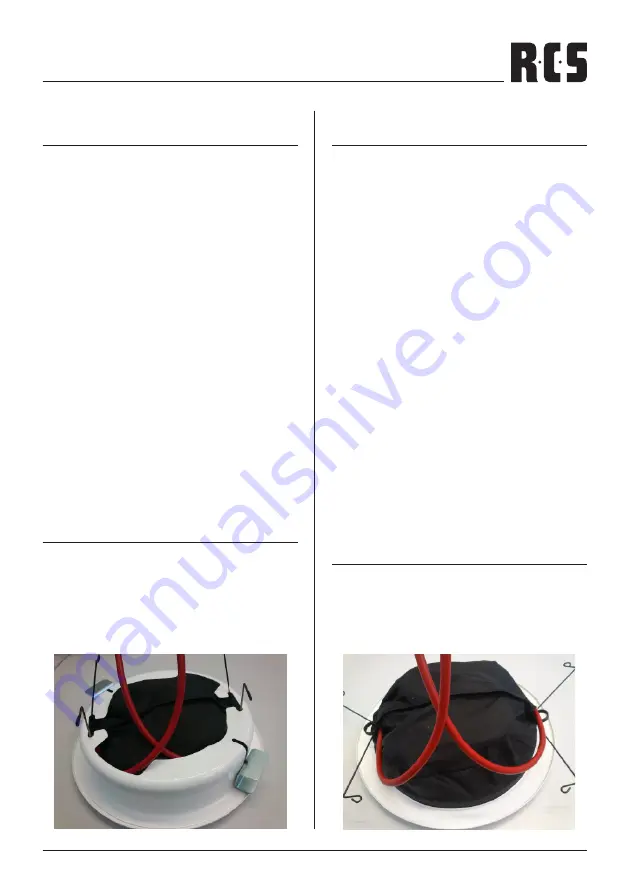
7. Take care to lay the cables in a way you see in the pic-
ture. These guarantees that no water can flow into the
loudspeaker area.
8. Reconnect the spring wires on the second side of the fire
dome.
9. Push the loudspeaker firmly in direction of the installati-
on ring. The spring wires will hold the loudspeakers at its
final position.
DisAssEMBly
To disassemble the speaker, go like described above in re-
verse order. To pull the speaker out of the installation ring
use a thin wire (with a L-bend) fitting into the speaker grid
and pull it out.
MoNtAgEANlEituNg
EiNBAu
Der benötigte Lochausschnitt für die Installation sollte einen
Durchmesser von 204 mm ±5 mm aufweisen. Die Einbautie-
fe sollte mindesten 100 mm betragen.
1. Entfernen Sie den Montagering von dem Lautsprecher
durch Lösen der Sprungklammern auf beiden Seiten.
2. Legen Sie den Montagering in die Montageöffnung und
befestigen Sie ihn, indem Sie zuerst die Flügelschrauben
lockern, die Halterung hinabschieben und dann die Flü-
gelschrauben nochmals festziehen.
3. Um die Kabel anzuschließen, ist es erforderlich, dass auf
einer Seite des Feuertopfs die Sprungklammer wieder
eingehängt wird.
4. Öffnen Sie den Klettverschluss der Abdeckhaube, um
die Kabel anzuschließen.
5. Verbinden Sie die Kabel wie es im Diagramm aufgezeich-
net ist.
6. Legen Sie die Klemmen zurück in die Abdeckhaube und
schließen Sie den Klettverschluss. Versichern Sie sich,
dass der Klettverschluss gut verschlossen ist, beson-
ders am Kabelausgang.
7. Achten Sie darauf, dass Sie die Kabel so legen, wie es im
Bild aufgezeichnet ist. Dies garantiert Ihnen, dass kein
Wasser in den Lautsprecherbereich eindringen kann.
7. Hängen Sie nun die Sprungklammer auf der anderen
Seite des Feuertopfs ein.
8. Drücken Sie die Lautsprecher fest in Richtung des Instal-
lationsrings. Die Sprungklammern werden die Lautspre-
cher in ihrer endgültigen Position halten.
AusBAu
Um die Lautsprecher auszubauen, gehen Sie bitte anhand
der Einbaubeschreibung vor, in umgekehrter Reihenfolge.
Um die Lautsprecher aus dem Installationsring zu lösen,
verwenden Sie eine dünne Klammer (mit L-Biegung). Führen
Sie diese in das Lautsprechergitter ein und ziehen dann den
Lautsprecher heraus.
Содержание RC-512 EN-1
Страница 6: ...RC 512 EN 1 6...


