


22 / 25
Section : 9 Troubleshooting
9.1
General Guidelines
This section informs the user how to quickly resolve an operational problem with the system.
During any troubleshooting phase, it will save time if the operator can firstly determine the
problem. Either it is related to the process controller, process sensor, or some external source.
Therefore, this section is organized from the approach of excluding any likely external sources,
isolating the transmitter and finally isolating the electrode. If these procedures still do not
resolve the operational problems, any results noted here will be very helpful when discussing
the problem with the factory technical support group.
•
Verify the proper power input is present (16 - 24V DC). Ensure the loads on the 4-20mA
outputs
don’t
exceed the limit (see section 1.3, 4.2).
•
Don’t put sensor cables or instrument 4
-20 mA output wires in the same conduit that
contains AC power wires. AC power wires should be run in a separate conduit to prevent
electrical noise from contacting with the instrumentation signals. Check for possible
ground loops. High frequency sources of electrical noise may cause abrupt behavior in
extreme conditions. If readings are very erratic after wiring has been checked, check for a
possible AC ground loop by temporarily moving the sensor to a sample of solution in a
beaker or other container.
9.2
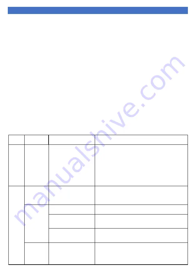
Troubleshooting Chart
ERROR
TYPE
ERROR
CODE
DESCRIPTION
TROUBLE SHOOTING
C
ali
bra
tio
n
Error 100
Cell constant out of range.
Calibration failed because
cell constant value is
either too high or too low.
Permissible range for cell
constant (
0.1 - 20
).
1- Clean probe by proper cleaning techniques.
(See section: 7.1 & 8.1.2)
2- Use valid buffer solutions.
(See section: 7.1 & 8.1.2)
3- Check probe for any physical damage.
(See section: 3 & 4.3)
4- Change the conductivity probe if it is damaged.
5- Enter proper conductivity value related to calibration
buffer solution.
G
ene
ra
l
White
Display
Low or high voltage /
display problem / contrast
not set / circuit board
issue
1- Check input voltage.
2- Set LCD contrast from display setting.
(See section: 8.1.1)
Blank
Display
Power not connected
Check input power connection.
(See section: 4.1, 4.2)
Power connections
polarity reversed
Check input power connections and reconnect in correct
polarity.
(See section: 4.1, 4.2)
Loose Power Connections
1- Check input power connection.
2- Tighten the power cables in terminal block.
(See section: 4.1, 4.2)
No
Conductivity
/ TDS Value
Display
Conductivity / TDS value is
too high or too low
1- Change the conductivity probe if it is damaged.
2- Clean probe by using proper cleaning techniques.
3- Perform calibration by using proper calibration
techniques.


