background image

4

Product Manual –

INTUITION HT

INSTALLATION

MASTER CONTROL UNIT (MCU)

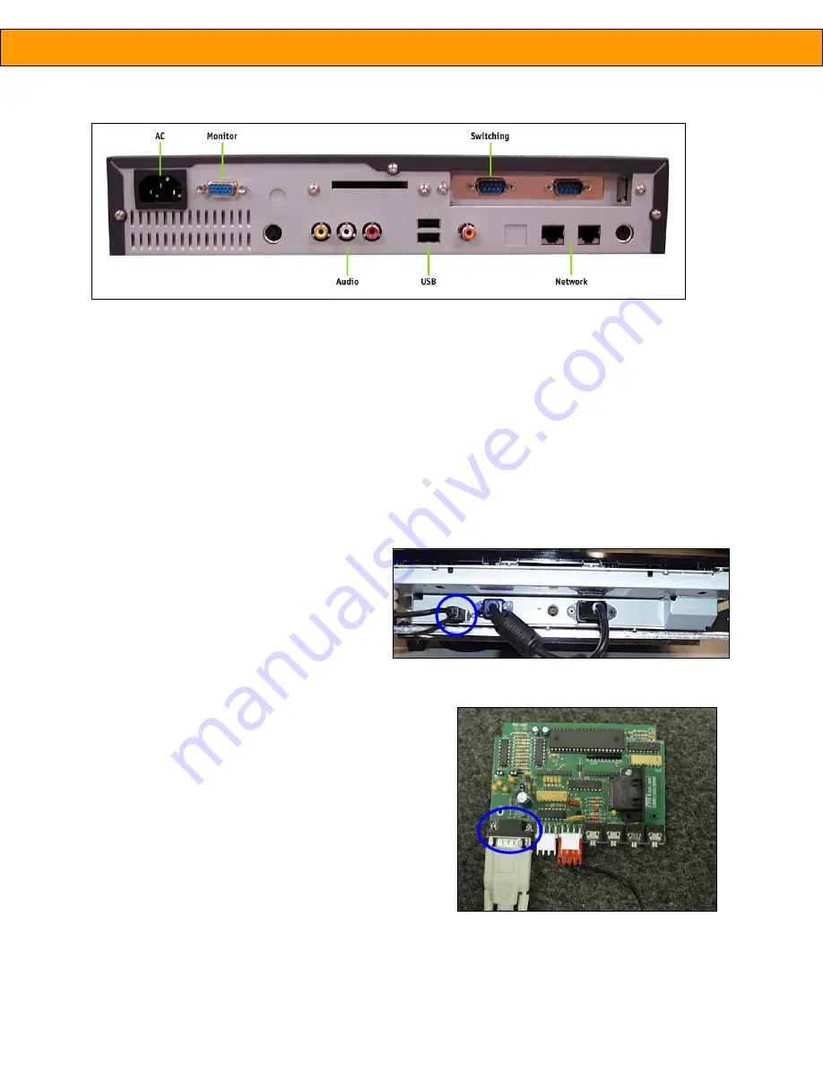
1.  Insert a USB cable into the top USB slot in middle rear of MCU (

indicated as USB in fig. 1). 

2.  Insert blue, male-ended VGA monitor cable from the touchscreen into female monitor port on the left rear of

the MCU 

(Monitor, fig. 1).

3.  Insert white/grey female-ended serial cable from the switching system into left male serial port 

(Switching,

fig. 1).

4.  Insert red and white male RCA cables into same color ports 

(Audio, fig. 1).

5.  Insert power cable into power port 

(AC, fig. 1).

TOUCHSCREEN

1.  Insert a USB cable from the MCU into the USB

slot on the bottom of the touchscreen (

circled

in fig. 2).

2.  Insert blue, male-ended VGA monitor cable

from the MCU into female monitor port on the
bottom of the touchscreen.

3.  Insert power cable into power port.

SWITCHING INTERFACE BOARD

1.  Insert white/grey female-ended serial cable from the MCU

into the interface board connected to your MTI switching
system. (

fig. 3)

fig. 1 – Master Control Unit

fig. 3 – Switching interface board

fig. 2 – Touchscreen

Содержание Intuition HT

Страница 1: ...00 426 6844 503 648 6500 503 648 7500 f 1050 NW 229th Avenue Hillsboro OR 97124 www mti interactive com MTI P N 063 0209 00 Rev B July 2004 PRODUCT MANUAL Intuition HT Home Theater Switching Application ...

Страница 2: ......

Страница 3: ...ly plays a video attract loop The attract loop is designed to grab the attention of a passing customer and thus increase traffic to the display Employee Training The system can help train employees by providing them the ability to test different audio system combinations PRODUCT DESCRIPTIONS GENERAL SPECIFICATIONS The system is comprised of the following major components Display fixture cabinet th...

Страница 4: ...sert red and white male RCA cables into same color ports Audio fig 1 5 Insert power cable into power port AC fig 1 TOUCHSCREEN 1 Insert a USB cable from the MCU into the USB slot on the bottom of the touchscreen circled in fig 2 2 Insert blue male ended VGA monitor cable from the MCU into female monitor port on the bottom of the touchscreen 3 Insert power cable into power port SWITCHING INTERFACE ...

Страница 5: ... select a product category e g A V Receivers from the top A list of numbers appears in the middle of the screen These numbers correspond to the component s position on the display fixture Use the scroll arrows to view all available models fig 5 3 Touch the component number to activate the component and add it to Your Home Theater room graphic in the lower right corner of screen Note When you add a...

Страница 6: ...ed systems 2 On the Pre configured systems screen select one of the systems Good Better or Best fig 7 3 The system selector screen appears All components for this system are added to your system 4 You can now modify this system using the steps outlined in the Building a System section above SELECTING AN AUDIO VIDEO SOURCE Once you have built your home theater system you can audition the system usi...

Страница 7: ...ouch the Start Here button to move to the Welcome screen 2 Touch the MTI logo upper left hand corner three times 3 A password prompt appears To operate the system in Manager Mode enter the Manager Mode password default from factory is 9751 then press Submit To operate the system in Super User Mode enter the Super User password 369258147 then press Submit Note You are given three tries to enter the...

Страница 8: ... notifies that the timeout has changed ENABLING DISABLING PRODUCTS There may be times when you need to disable a product in the display e g product is temporarily unavailable because it has been sold removed from the display and then later re enable it To enable or disable products 1 From the Manager Control Panel touch Configure Positions 2 Select a product category e g A V Receivers from list on...

Страница 9: ...t included on the system selector screen and is not available to the customer 3 Use the 1 5 1 5 buttons to set the number of products in each category For example if there are eight A V receivers in the display set the of positions to 8 When a customer selects A V Receivers on the system selector screen they will now see eight products represented by numbers 1 8 fig 13 4 Press the Test Chain butto...

Страница 10: ...operly these sources must be matched to a specific source position associated with the display To set the sources 1 From the Manager Control Panel touch Set Sources 2 Assign each audio visual source to the desired position fig 13 Example of enabled chains and number of products in the chain all enable chains appear as tabs on the system selector screen number of products in the chain ...

Страница 11: ...tached to the MCU and that it is not damaged Touchscreen does not display User Interface after completion of the boot sequence USB cable may be damaged or attached incorrectly Ensure that the USB cable is connected to the MCU and touchscreen Touchscreen does not respond to user Touchscreen may be damaged Check for damage to the touchscreen housing or cabling connections Error message appears on th...

Страница 12: ... represents the only Warranty for MTI manufactured products No other Warranty expressed or implied exists No modifications other than those mandated by formal written contract may be made to this Warranty In no event will MTI be liable for any damages including but not limited to lost profits lost sales incidental or consequential damages arising out of the use of MTI products Some states do not a...

Отзывы: