UM-1096
Revision A
9
3.5
Remote Sensor Installation
3.5.1
SensePoint Remote Sensor
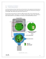
Use of the Remote Sensor Option Board requires the SensePoint to be equipped with a RS 485 Option or
Relay Option Board. The Remote Sensor Option Board communicates to the SensePoint by utilizing one
of the RS-485 communication ports located on the option board.
Connect 24VDC and ground wires to the 24V and GND terminals on TB1 or TB2 of the Remote Sensor
Option Board to supply the necessary 24V. Connect the A and B terminals of TB1 or TB2 of the Remote
Sensor Option Board to the A and B Master Port terminals of the Relay/RS-485 Option Board.
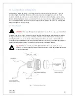
Figure 6 Remote Sensor Option
Содержание 10-0517
Страница 4: ...UM 1096 Revision A III Drawings 44...
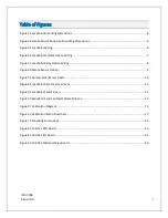
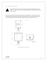
Страница 10: ...UM 1096 Revision A 5 Figure 2 Remote Sensor Enclosure Mounting Dimensions...
Страница 26: ......
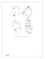
Страница 49: ...UM 1096 Revision A 44 Appendix 9 Drawings Drawings Figure 13 Mounting Dimensions...
Страница 50: ...UM 1096 Revision A 45 Figure 14 10 0517 CPU Board Figure 15 10 0533 I O Board...
Страница 51: ...UM 1096 Revision A 46 Figure 16 10 0532 Modbus Relay Board...


