background image

This manual is intended only for use by a qualified heating installer/technician. Read and follow this manual, all supplements and related 

instructional information provided with the boiler. Install, start and service the boiler only in the sequence and methods given in these 

instructions. Failure to do so can result in severe personal injury, death or substantial property damage.

Do not use the boiler during construction.

 Construction dust and particulate, particularly drywall dust, will cause contamination of 

the burner, resulting in possible severe personal injury, death or substantial property damage.  The boiler can only be operated with a dust-

free air supply. Follow the instruction manual procedures to duct air to the boiler air intake. If the boiler has been contaminated by operation 

with contaminated air, follow the instruction manual guidelines to clean, repair or replace the boiler if necessary.

Affix these instructions near to the boiler/water heater. Instruct the building owner to retain the instructions for future use by a qualified 

service technician, and to follow all guidelines in the User’s Information Manual.

1

0/16

 Copyright 2015 Mestek, Inc.

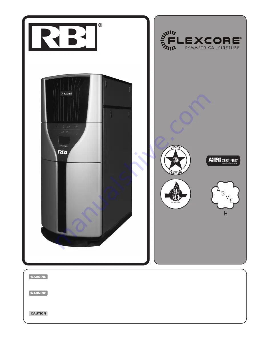
Stainless Steel Condensing Boilers 

Models CK1500, CK2000, CK2500, 
CK3000, CK3500, CK4000, CK4500, 
CK5000 & CK6000

Boiler Manual

Installation and Operation 
Instructions

FCR-IOM-5

82-0651

Also read and follow:

HeatNet Control Manual

Содержание FlexCore CK 1500

Страница 1: ...antial property damage The boiler can only be operated with a dust freeairsupply Followtheinstructionmanualprocedurestoductairtotheboilerairintake Iftheboilerhasbeencontaminatedbyoperation with contaminated air follow the instruction manual guidelines to clean repair or replace the boiler if necessary Affix these instructions near to the boiler water heater Instruct the building owner to retain th...

Страница 2: ... PSI 1103 kPa WATER INSTALLER THESE INSTRUCTIONS TO BE AFFIXED ADJACENT TO THE BOILER WATER HEATER CONSUMER RETAIN THESE INSTRUCTIONS FOR FUTURE REFERENCE PURPOSES CONTENTS Before Your Start page 2 Ratings Capacities page 3 Location page 3 Combustion Air Ventilation page 3 Venting Guidelines page 5 Common Vent Systems page 15 General Piping Requirements page 16 Heating System Piping page 17 Domest...

Страница 3: ...ut never on carpeting 4 Locate the boiler in an area that will prevent water damage to adjacent construction should a leak occur or during routine maintenance 5 DO NOT place this boiler in a location that would restrict the introduction of combustion air into the unit or subject it to a negative pressure unless the combustion air is piped from the outside see the COMBUSTION AIR VENTILATION section...

Страница 4: ...t The upper opening must be within 12 in 300 mm of but not less than 3 in 80 mm from the top of the enclosure The bottom opening must be within 12 in 300 mm of but not less than 3 in 80 mm from the bottom of the enclosure Where directly communicating with the outdoors or communicating with the outdoors through vertical ducts each opening shall have a minimum free area of 1in2 4000 Btu hr 550 mm2 k...

Страница 5: ...pressure vent systems can result in excessive levels of carbon monoxide which can cause severe personal injury or death A barometric damper or blast gate as required must be installed if a Category II vertical vent system produces a negative draft in excess of 0 10 in 2 5 mm WC at the flue outlet Size the vent system per local codes and the vent pipe manufactuers requirements using generally accep...

Страница 6: ... vent systems Do not mix vent systems of different manufacturers Use only listed manufacturers Table X terminations Table Y and transition adapters Table Z The chimney systems manufacturer s installation instructions must be followed Model Outlet Diameter K 1500 2000 2500 3000 3500 4000 4500 5000 6000 6 6 8 8 10 10 10 12 12 Maximum Equivalent Length Catagory IV 100 100 100 100 100 100 100 100 100 ...

Страница 7: ...wall metal vent system passes through an unheated space it must be insulated with insulation rated for 400 F 204 C Structural penetrations must be made using approved fire stops The top of a vertical vent system must extend at least 51 2 ft 1 8 m above the roof surface that it passes through 4 ft 1 3 m above the intake air cap see Figure 4 In addition the vent system must conform to the dimensions...

Страница 8: ...ORR GUARD Security Chimneys Secure Seal Schebler Chimney Systems e Vent VAN PACKER CS Z Flex Z Vent Jeremias GOV ICC VIC Exhaust Termination Hood Exhaust 90 deg Exhaust Tee Exhaust 45 deg Exhaust Straight with bird screen Table X Approved Stainless Steel Vent Manufacturers CAT II IV Table Y Approved Intake Exhaust Terminations CAT IV Sidewall Horizontal Direct Vent ...

Страница 9: ...KL 09 00002 002 09 0112 2000 2500 9801MAD SS8FFNSAU SSD8FFNSAUK SWKL8 S2D 09 00002 001 09 0113 3000 3500 91001MAD SS10FFNSAU SSD10FFNSAUK SWKL10 S2D 09 0310 004 09 0115 4000 4500 5000 91201MAD SS12FFNSAU SSD12FFNSAUK SWKL12 S2D 09 0310 005 09 0116 6000 Model Size VAN PACKER Z Flex Schebler Chimney Systems e Vent Transition Adapter Flue Transition Adapter Flue Transition Adapter Flue 1500 C06VLSL M...

Страница 10: ... practices and the design calculations prove there is no need for barometric dampers the barometric dampers may be omitted When required by applicable codes install a thermal spill switch on each barometric damper 1 Connect each boiler riser to the common vent with a Y connection or Boot T only 2 Install an approved vent cap at each vent termination 3 Dimensions B breeching length C chimney height...

Страница 11: ...ainless Steel Condensing Boilers Installation Manual Figure 2 Horizontal Air Intake and Venting for a Single Direct Vent System Figure 3 Horizontal Air Intake and Venting for Multiple Direct Vent Systems 10 ft 3 1 m ...

Страница 12: ...ensing Boilers Installation Manual Figure 4 Vertical Air Intake and Venting for Direct Vent System Figure 5 Combination Direct Vent Systems 10 FT 3 1 m 4 FT 1 2 m 5 FT 1 5 m 1 5 FT 0 5 m 5 1 2 FT 1 7 m 1 5 FT 5 m 10 FT 3 1 m 3 FT 1 m ...

Страница 13: ...ZONTAL DIRECT VENT SYSTEMS section must also be followed Figure 6 Side Wall Venting VERTICAL VENT Recommended POSITIVE PRESSURE CATEGORY IV In this configuration the boiler blower is used to push the flue products vertically to the outdoors see Figure 7 The air for combustion is taken from the space in which the unit is installed The applicable instructions under the COMBUSTION AIR VENTILATION SEC...

Страница 14: ...s listed as a Category II appliance when vented vertically into a listed metal AL294C S S chimney system Figure 8 The chimney system must provide a negative pressure of 0 02 to 0 10 in 0 51 to 2 5 mm WC at the boiler flue collar with the unit running When using a listed metal chimney system the chimney system manufacturer s instructions must be followed Multiple boiler vent systems must be designe...

Страница 15: ...tes entre l espace où les appareils toujours raccordés du système d évacuation sont installés et les autres espaces du bâtiment Mettre en marche les sécheuses tous les appareils non raccordés au système d évacuation commun et tous les ventilateurs d extraction comme les hottes de cuisinère et les ventilateurs des salles de bain S assurer que ces ventilateurs fonctionnent à la vitesse maximale Ne p...

Страница 16: ...OSURE OF PERSONS TO HOT LIQUID OR VAPOR AND FOLLOW COMPLETE DRAINAGE OF RELIEF TEMPERATURE GAUGE RIOM 0213_01A CONDENSATE DRAIN AIR VENT AIR VENT CONDENSATE DRAIN ASSEMBLY PRESSURE RELIEF VALVE FLOW SWITCH SUPPLY OUTLET RETURN INLET FLUE OUTLET LOW WATER CUTOFF ASSEMBLY HI LIMIT VALVE AND PIPING PRESSURE RELIEF VALVE DISCHARGE SO AS TO AVOID EXPOSURE OF PERSONS TO HOT LIQUID OR VAPOR AND FOLLOW CO...

Страница 17: ...86 6 433 1 43 3 5000 95 9 479 7 48 0 6000 116 2 581 0 58 1 Min Maxflowcorrespondtoa 20 F 100 F Δtatfullinput for applications requiring operation above and or below these parameters please consult manufacturer HEATING SYSTEM PIPING General Piping Requirements All heating system piping must be installed by a qualified technician in accordance with the latest revision of the ANSI ASME Boiler and Pre...

Страница 18: ...ter than 300 ppm hardness Suspended solids such as Magnetite Iron Oxides must be flushed from the system prior to commissioning the boiler s The PH level must be within the 6 5 10 range Where required the system must be protected by the addition of a corrosion inhibitor per the chemical supplier s instructions For systems requiring glycol for freeze protection use a glycol water mix that prevents ...

Страница 19: ...zed Valve FOR HEAT NET OPERATION A SENSOR IS REQUIRED AND INSTALLED AT A MINIMUM OF 12 FROM PRIMARY LOOP TEE RIOM 0205_A TANGENTIAL TYPE AIR SEPARATOR AQUASTAT HEAT NET SENSOR PRESSURE REDUCING VALVE PRESSURE RELIEF VALVE EXPANSION TANK THERMOMETER BACKFLOW PREVENTION DEVICE GATE VALVE PUMP SYSTEM RETURN AIR SEPARATOR TYPICAL LOCATION AIR SEPARATOR ALTERNATE LOCATION MOTORIZED VALVE M M M M M SYST...

Страница 20: ... domestic use above 140 F 60 C will provide an increased quantity of tempered water and help prevent the growth of water born bacteria Figure 14 Typical Single Boiler with Indirect Storage Tank Piping RIOM 0206_A HEAT NET SENSOR EXPANSION TANK THERMOMETER BACKFLOW PREVENTION DEVICE GATE VALVE PUMP TEMPERATURE PRESSURE RELIEF VALVE PRESSURE RELIEF VALVE CHECK VALVE VACUUM RELIEF VALVE NOTES 1 LOCAT...

Страница 21: ...PIP 4 HOT WATER PRESSURE R REFER TO L 5 MA CODE RE 6 CONTRACTO OF AN ACID N NOTICE THE DIAGRAMMA COLD WATER MAKE UP FILL SUPPLY CIRCULAR RETURN FLOW FLOW BRONZE PUMP COLD WATER MAKE UP FLOW FLOW 4 1 2 3 2 5 5 RIOM 0207_A HEAT NET SENSOR EXPANSION TANK THERMOMETER E E PRESSURE RELIEF VALVE VACUUM RELIEF VALVE NOTES 1 LOCATE HEAT NET SENSOR WITH WELL IN LOWER 1 3 OF TANK INSTALL SENSOR WITH HEAT SEN...

Страница 22: ...extensive property damage severe personal injury or death The FlexCore comes from the factory ready to be piped to the gas supply If for any reason the boiler is not for the type of gas available at the installation site call your RBI representative to resolve the problem Table 8 should be used to ensure that the gas supply piping is sized properly If more than one appliance is supplied by the sam...

Страница 23: ...ld wiring of any controls or other devices must use copper conductors with a minimum size of 14 awg Refer to point of connection diagram in back of this manual and the wiring diagram supplied with the boiler for proper wiring connections Table 9 Equivalent Pipe Length Chart A lockup style regulator supplied by others must be installed see Figure 17 if gas pressure exceeds 14 in WC The regulator wh...

Страница 24: ...GAS SUPPLY SEDIMENT TRAP AND DRIP LEG SUPPLIED BY OTHERS 002 PIPING GAS SUPPLY CK 3500 T 6000 SHOWN PILOT REGULATOR AND SOLENOID VALVE TEST PORT MODULATING GAS VALVE LOW FIRE GAS PRESSURE ADJUSTMENT HIGH FIRE GAS PRESSURE ADJUSTMENT HIGH GAS PRESSURE SWITCH MANUAL SHUTOFF VALVE 1 MANUAL SHUTOFF VALVE 2 LOW GAS PRESSURE SWITCH CSD 1 TEST PORTS PRESSURE REGULATOR PILOT SHUT OFF VALVE MANUAL SHUTOFF ...

Страница 25: ...ose the make up water valve and check and clean the strainers and make up water pressure reducing valve Open the make up water valve and adjust the system pressure if necessary The system should be checked and bled after three days of operation OPERATING INSTRUCTIONS FOR YOUR SAFETY READ BEFORE OPERATING ONLY QUALIFIED LICENSED SERVICE TECHNI CIANS SHALL START TROUBLESHOOT AND SERVICE THIS APPLIAN...

Страница 26: ... when the power is on If all interlocks are properly closed the display will say Standby Figure 18 13 Slide the HeatNet controls low fire switch on the HeatNet control board to the low fire position 14 The boiler will begin the start sequence 15 When the main display reads PILOT RUNNING and the flame current is 5VDC switch the Honey well 7800 test run switch into the test position Figure 18 This w...

Страница 27: ...etected and the 7800 should lock out If flame current is detected at any time up to the 7800 locking out the 120V wiring on the ignition transformer must be reversed and the test run again to insure that no flame is detected Improper wiring of the ignition transformer can result in an explosion causing extensive property damage severe personal injury or death 23 Open both manual main shut off valv...

Страница 28: ...ng that it can be changed Adjust the maximum value using the arrow keys to achieve the required combustion CO2 O2 Table 11 and pressure delta p Table 12 c The high fire trim adjustment is located on the outlet flange Figure 17 of the gas valve d When the adjustment is satisfactory press the check key to save the setting Follow the same procedure for the rear module on units CK3500 CK6000 When comp...

Страница 29: ...uired allow 0 2 range adjustment Note When units are installed with direct sealed combustion air during periods of time with low outdoor temperature it is possible for the room air to condense and possibly form frost on the air handling components of the boiler Refer to 2015 ASHRAE Cold Climate Buildings Design Guide Table 11 Combustion Settings Table 12 Pressure Signal P Nat Gas Firing Rate 1500 ...

Страница 30: ...ast limit in the Limit String to Ignition Control Have We received the BLOWER signal CALL FOR HEAT PRE_PURGE Interlocks OK Are we below the Temp Band YES fire the boiler NO Send 120 VAC BLOWER signal Limits OK Operate Blower Motor 55 LIMITS After 10 Seconds send PILOT signal BLOWER PILOT signal PILOT PILOT Ignition J4 Pins 4 8 Operate Blower Motor 32 FLAME Operate Blower Motor 0 After 10 Seconds s...

Страница 31: ...ions of the Honeywell 7895C s amplifier with a dc voltmeter CHECKING ADJUSTMENT OPERATION Spark Gap The gap has to be measured and adjusted with the igniter removed from the boiler Observe the trial for ignition to confirm that the spark is strong and continuous If not allow the electrodes to cool Check and adjust the spark gap as shown in Figure 19 Electrode tips should face slightly downward Fig...

Страница 32: ...hat the low water cutoff device s function properly Test in accordance with the manufacturer s instructions included with the device s DIAGNOSTICS The FlexCore has a display that indicates the sequence of operation Figure 18 The display will also list faults should the unit fail to operate An explanation of each fault is listed below STANDBY Indicates that power is being supplied to the unit and t...

Страница 33: ...system piping Inspect the air filter and replace when required Controls Use the BOILER OPERATION and CHECKING AND ADJUSTMENT sections of this manual for reference 1 Check the operating controls for proper operation 2 A float type low water cutoff device must be flushed out per the manufacturers instructions The probe on a probe low water cut off must be removed cleaned and inspected at least once ...

Страница 34: ...ED INLET 3 0 LEGEND FLEXIBLE PLASTIC TUBING POSITIVE PRESSURE TAP NEGATIVE PRESSURE TAP PILOT VALVE ASSEMBLY ASCO AIR SHUT OFF VALVE UV SCANNER AIR PUMP AIR BOX DIFFERENTIAL PRESSURE PILOT GAS PILOT AIR NOTES 1 TYPICAL PER EACH INDIVIDUAL MODULE 2 EACH MODULE HAS A UNIQUE BLOWER PROVE AND BLOCKED FLUE SWITCH ONE COMMON BLOCKED INLET SWITCH IS USED FOR ALL MODULES C C PRESSURE SWITCH BLOWER PROVE C...

Страница 35: ...35 FlexCore Stainless Steel Condensing Boilers Installation Manual Figure 23 RBI Field Wiring to HeatNet Board 3 0 ...

Страница 36: ...0 41 42 43 24 22 21 20 23 18 17 19 47 44 SEE VIEW E SEE VIEW C SEE VIEW B SEE VIEW A 25 SEE VIEW D 46 48 51 1 1 2 3 5 9 8 11 7 6 7 6 6 6 45 49 50 41 42 43 SEE VIEW D 51 2 1 1 1 1 2 2 3 3 5 4 5 9 8 10 11 7 6 6 6 6 7 7 7 6 6 6 6 VIEW A Figure 24 Single Unit Replacement Parts ...

Страница 37: ...37 FlexCore Stainless Steel Condensing Boilers Installation Manual VIEW B VIEW C VIEW B VIEW C VIEW E VIEW D VIEW D VIEW E ...

Страница 38: ... 1 1 1 1 23 Front LH Panels 75 0028 001 1 1 1 1 24 Front Top Panel 75 0025 001 1 1 1 1 25 Front Air Inlet 74 0015 001 1 1 1 1 41 Rear Panel 03 4524 001 1 1 1 1 42 Filter Box 75 0018 001 1 1 1 1 43 Filter Filter Box 1 1 1 1 44 Main Frame 74 0001 001 1 1 1 1 45 LWCO 14 0258 1 1 1 1 46 Touchscreen 40 0090 1 1 1 1 47 Front Panel 1 1 1 1 47A Front Top Panel 75 0032 1 1 1 1 47B Front Center Panel 75 003...

Страница 39: ... 11 0223 1 1 1 1 80 Outlet Flange 11 0229 1 1 1 1 81 High Gas Pressure Switch 11 0421 1 1 1 1 82 Firing Valve 11 0458 1 1 1 1 83 Pilot Orifice 10 0140 003 1 1 1 1 84 Gas Valve 11 0079 1 1 1 1 85 Air Solenoid Valve 11 0376 1 1 1 1 86 Mini Fan 12 0021 002 1 1 1 1 87 Air Pressure Switch 14 0067 1 1 1 1 88 Air Pressure Switch 2 5 WC 14 0068 1 1 1 1 89 Air Pressue Switch 3 WC 14 0069 1 1 1 1 90 Air Pum...

Страница 40: ...6 45 16 15 20 21 22 23 24 19 18 17 44 33 25 32 29 28 30 31 43 42 41 27 26 49 50 51 SEE VIEW A SEE VIEW B SEE VIEW D SEE VIEW E SEE VIEW C 1 1 1 2 2 5 5 5 4 4 5 3 3 6 6 14 6 6 6 7 7 6 6 7 1 1 1 4 12 6 14 6 5 7 13 4 7 5 6 13 12 6 5 5 6 7 Figure 25 Double Unit Replacement Parts ...

Страница 41: ...41 FlexCore Stainless Steel Condensing Boilers Installation Manual VIEW B VIEW C VIEW E VIEW D VIEW E VIEW D VIEW B VIEW C ...

Страница 42: ...ls 75 0027 002 1 1 1 1 1 23 Front LH Panels 75 0028 002 1 1 1 1 1 24 Front Top Panel 75 0025 002 1 1 1 1 1 25 Front Air Inlet 74 0015 002 1 1 1 1 1 26 2XR 3XM RH Panels 75 0028 008 1 1 1 1 1 27 2XR 3XM RH Panels 75 0027 008 1 1 1 1 1 28 2XR 3XM LH Panels 75 0028 003 1 1 1 1 1 29 2XR 3XM LH Panels 03 4520 001 1 1 1 1 1 30 2XR 3XM LH Panels 75 0027 003 1 1 1 1 1 31 2XR 3XM Top Panel 75 0025 003 1 1 ...

Страница 43: ...75 1 1 1 1 1 74 Expansion Joint 3 53 5050 006 1 1 1 1 1 75 Expansion Joint 4 76 Gas Shut Off Valve 11 0467 2 2 2 2 2 77 Inlet Flange 11 0214 2 2 2 2 2 78 Low Gas Pressure Switch 11 0422 2 2 2 2 2 79 Gas Valve 11 0223 2 2 2 2 2 80 Outlet Flange 11 0229 2 2 2 2 2 81 High Gas Pressure Switch 11 0421 2 2 2 2 2 82 Firing Valve 11 0458 2 2 2 2 2 83 Pilot Orifice 10 0140 003 2 2 2 2 2 84 Gas Valve 11 007...

Страница 44: ... Disable any external call for heat and toggle the remote local switch to REMOTE 1 Toggle the LOW FIRE switch to cycle the boiler then hold at trial for pilot ignition 2 Set pilot pressure follow section Checking Adjustment Operation flame signal should read 5 0 VDC 3 Release boiler to main flame trial for ignition 4 Check for stable flame 5 Record combustion and Delta P at minimum firing rate 6 J...

Страница 45: ... LOW WATER CUT OFF HIGH LIMITS COMMISSIONING THE BOILER UNIT CYCLED MINIMUM OF 15 TIMES THE DELTA T BETWEEN THE HEATER IN LET AND OUTLET IS CRITICAL TO PROP ER FLOW BEFORE YOU LEAVE THE JOB SITE YOU MUST RECORD THE DELTA T THIS READING SHOULD NOT EXCEED 100o o C NOR BE LOWER THAN 20o F 11 1o C DELTA T CUSTOMER INSTRUCTED ALL COVERS REPLACED CUSTOMER GIVEN MANUAL TARGET TEMPERATURE SET PER CUSTOMER...

Страница 46: ...all exhaust vent termination is less than seven 7 feet above finished grade in the area of the venting including but not limited to decks and porches the following requirements shall be satisfied 1 INSTALLATION OF CARBON MONOXIDE DETECTORS At the time of installation of the side wall horizontal vented gas fueled equipment the installing plumber or gasfitter shall observe that a hard wired carbon m...

Страница 47: ...In addition pH levels must be in the 6 5 10 range Failure to follow these guidelines will void the warranty This Limited Warranty does not Apply a If the product has been subjected to misuse or neglect has been accidentally or intentionally damaged has not been installed maintained or operated in accordance with the furnished written instructions or has been altered or modified in anyway by any un...

Страница 48: ...www rbiwaterheaters com 260 North Elm Street 7555 Tranmere Drive Westfield MA 01085 Mississauga Ontario L5S 1L4 Canada Phone 413 568 9571 Phone 905 670 5888 Fax 413 568 9613 Fax 905 670 5782 ...

Отзывы: