background image

Compact 4Ch H.264 Network DVR-MU.Ver1.1 

89 


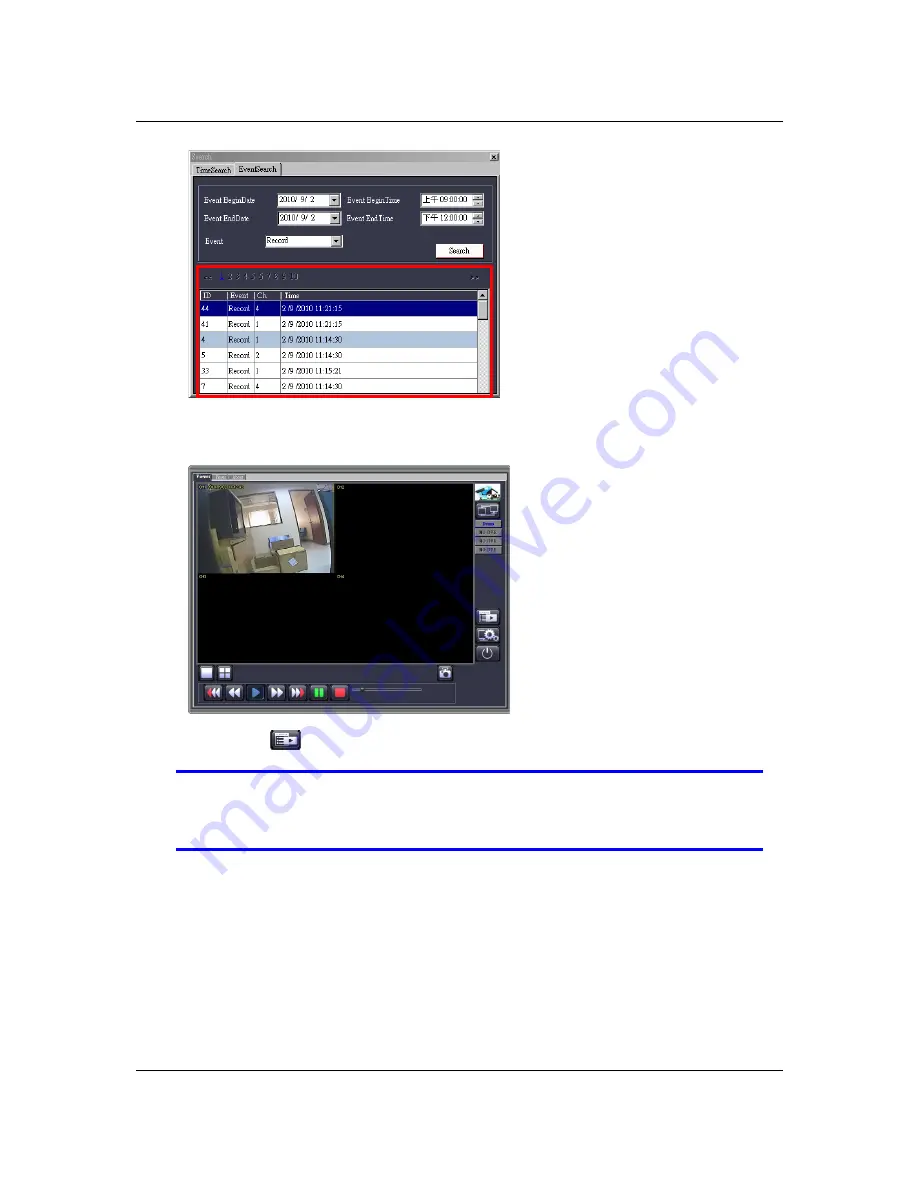
Playbacks the event by mouse double clicks. You will see the video playback as 
following figure: 


Click on the 

 icon back to “Event Search” control window. 

NOTE 

The “Record” and “Normal” events incorporate with video data for 
playback.  The “Hardware” and “Warning” event just present the 
occurred time. 

Содержание RVH3004

Страница 1: ...Compact 4Ch H 264 Network DVR Series MU Ver1 1 Compact 4 Channel H 264 Network DVR Series User Guide ...

Страница 2: ...Compact 4Ch H 264 Network DVR Series MU Ver1 1 ii ...

Страница 3: ...4 Network DVR Series MU Ver1 1 iii Publication History Version Date Description 1 0 27 July 2010 Initial Release 1 1 12 August 2010 Add new function for Limitable Recording Days Calendar Search PC Viewer and Web Viewer ...

Страница 4: ... used in accordance with the instruction manual may cause harmful interference to radio communications Operation of this equipment in a residential area is likely to cause harmful interference in which case the user will be required to correct the interference at his own expense CE This product is marked with the CE symbol and indicates compliance with all applicable directives WEEE DIRECTIVE PROD...

Страница 5: ... likely to be walked on or pinched by items placed against them paying particular attention to cords at plugs receptacles and the point where they exit the product Overloading Do not overload wall outlets extension cords or integral convenience receptacles as this can result in a risk of fire or electrical shock Lightning For added protection for this product during storm or when it is left unatte...

Страница 6: ...ng Do not attempt to service this product Opening or removing covers may expose the user to dangerous voltage or other hazards Refer all servicing to qualified personnel Safety Check Upon completion of any service or repairs to this unit ask the service technician to perform safety checks to determine that the unit is in proper operating condition ...

Страница 7: ... to alert the user to the presence of important operating and maintenance servicing instruction in the literature accompanying the product USERS OF THE SYSTEM ARE RESPONSIBLE FOR CHECKING AND COMPLYING WITH ALL FEDERAL STATE AND LOCAL LAWS AND STATUTES COIPCERNING THE MONITORING AND RECORDING OF VIDEO AND AUDIO SIGNALS PANACOM SHALL NOT BE HELD RESPONSIBLE FOR THE USE OF THIS SYSTEM IN VIOLATION O...

Страница 8: ...Compact 4Ch H 264 Network DVR Series MU Ver1 1 viii ...

Страница 9: ...13 3 2 Home Screen 13 3 2 1 State Bar Information 14 3 2 2 Control Bar Information 15 3 2 3 Drag and Drop Channel Swap 15 3 3 Main Menu 16 3 4 Channel Setup 18 3 4 1 Channel Number 18 3 4 2 Basic Settings 18 3 4 3 Standard Color Adjustment 21 3 5 Record Setup 21 3 5 1 Auto Record 22 3 5 2 Record Schedule 22 3 5 3 Total Power 25 3 5 4 Auto Settings Adjustment 26 3 5 5 Channel Recording Setup 26 3 6...

Страница 10: ...3 11 2 Exit Discard Changes 56 4 Playback and Data Backup 57 4 1 Calendar Menu 58 4 2 Play Menu 59 4 3 Event Search 61 4 4 Data Backup 63 5 System Information 65 5 1 Record Information 66 5 2 Hard Drive Information 67 5 3 Network Information 68 6 LAN Online Viewing Setup 69 6 1 PC Connection through Local Area Network 70 6 2 DynDNS Service Overview 72 6 2 1 Register with DynDNS 72 6 2 2 Create Dyn...

Страница 11: ... 6 Playback the PVF File Backup from DVR side 97 7 1 7 Remote Playback 99 7 1 8 Remote DVR Configuration 102 7 2 Web Browser Viewer 103 7 2 1 Switching the Channel Displays 106 7 2 2 Web Browser Viewer Operation 106 8 SecuViewer 107 8 1 iPhone Environment 108 8 2 Install SecuViewer 108 8 3 SecuViewer Interface Overview 109 8 4 Connect to the DVR 110 ...

Страница 12: ......

Страница 13: ...Compact 4Ch H 264 Network DVR MU Ver1 1 1 Chapter 1 1 Overview ...

Страница 14: ...nel H 264 network DVR is designed in two versions with keypad and without keypad 1 2 Rear Panel Connector The rear panel of the DVR contains virtually all of the connectors you will be using The diagrams below outline the location and description of each connector 5 1 2 3 4 6 7 ...

Страница 15: ...C connector for video input 2 IR_ext IR extender connector optional 3 VGA OUT The VGA output DB 9 port for the LCD monitor 4 DC IN 12V DC power port for the power adaptor 5 VIDEO OUT Video output port for the security monitor 6 LAN The RJ45 port for the network cable 7 MOUSE The mouse port for USB mouse ...

Страница 16: ...cording of playback 7 FF Fast forward through video 8 PLAY Start video playback 9 MENU Enter a menu or exit 10 UP DOWN LEFT RIGHT Move through lists or change the settings of choices 11 Enter Select Change and confirm values 12 AUTO Start automatic screen view rotation 13 MODE Changes to split screen mode 14 ZOOM OUT Not available in DVR mode 15 ZOOM IN Not available in DVR mode 16 1 2 16 Channels...

Страница 17: ...Compact 4Ch H 264 Network DVR MU Ver1 1 5 Chapter 2 2 Installation ...

Страница 18: ...llation The same hard drive installation method is used for either version of the DVR The DVR contains one internal hard drive side bracket and is used for installing a SATA hard drive Install the hard drive by following steps Unscrew one screw at the top side of DVR housing Unscrew the five screws on the bottom side of the DVR housing ...

Страница 19: ...on to remove Attach the SATA HDD data cable into the Hard Drive data slot Location J16 as indicated in the following drawing Attach the SATA HDD power cable into the HDD power slot Location PJ2 as indicated in the following drawing J16 Connected with SATA HDD data cable PJ2 Connected with SATA HDD power cable ...

Страница 20: ...disk are aligned with the holes for the screws of the side bracket please use the following drawing for reference Secure the hard drive to the side bracket using two screws Fasten two more screws to bottom side of DVR to secure the hard drive The placement screws are indicated in the following drawing The hard drive side bracket 1 2 No connector side of hard drive ...

Страница 21: ...4Ch H 264 Network DVR MU Ver1 1 9 Push the cover down and slide back as indicated by the arrow in the illustration into place Fasten one screw on the top housing and four screws on the bottom housing to secure ...

Страница 22: ...ct the Security Camera Connect the security cameras to the video inputs labeled as CH1 to CH4 on the DVR This connection provides the DVR with the surveillance video input Connect the Security Monitor Connect the security monitor to the video output labeled as VIDEO OUT on the DVR The connection provides a video transmission path from the DVR to the security monitor Connect the Network Cable Conne...

Страница 23: ...ort labeled as IR_ext on the DVR The cable is an optional device which serves as an IR controller extension Connect the LCD Monitor Connect the LCD monitor to the VGA output labeled as VGA OUT on the DVR The DVR will transmit the video signal to the LCD monitor through this connection Connect the Power Adaptor Connect the Power Adaptor to the DC jack labeled as DC IN 12V on the DVR Connect the pow...

Страница 24: ...12 Chapter 3 3 Getting Started ...

Страница 25: ...on of the hard drive 1st time to install the HDD in the DVR Do not format the hard drive when The hard drive has already been formatted by the DVR and not formatted by other devices The Home Screen is shown after the system is ready 3 2 Home Screen The Home Screen is the starting point for many functions and applications It allows you to setup access and control the surveillance video data You may...

Страница 26: ...on Function Icon Function Camera is working No signal from camera Recording Stop recording Network connected Network disconnected USB disk connected Hard drive status Hard drive overwrite enabled Channel display rotation enabled XX Percentage of hard drive already used 2010 06 03 Current date 15 37 47 Current time 1 2010 06 06 15 37 47 1 2010 06 06 15 37 47 ...

Страница 27: ...ys can only be swapped by interchanging BNC connectors With Drag and Drop Channel Swap you can switch channel display positions using your mouse Drag and Drop Channel Reposition Move the cursor onto the channel square you would like to shift Icon Function Icon Function Load default channel display location 4 channel split view Auto channel rotation Start recording Stop force recording Start force ...

Страница 28: ...ew channel display arrangement even if you reboot the DVR system Load Default Location Press the icon to reset channel displays to their default locations 3 3 Main Menu Logging In for the First Time Press then enter the password to get into the main menu Default password is 123456 Enter Main Menu Password _ _ _ _ _ _ 0 1 2 3 4 5 6 7 8 9 Press to exit the password dialog 1 2010 06 06 15 37 47 1 201...

Страница 29: ... Set the motion and alarm mode Authentication Setup Set the login account password and the authentication System Setup Set the status icons display languages date time rotation time button beep tone input device speed and other relevant system features Hardware Setup Configures error message checks hard drive information overwrite settings network settings and screen settings Utility Tools These a...

Страница 30: ...settings will be applied to all channels Press the icons to individually set each channel The channel icon will turn green when selected and will turn to white when not selected 3 4 2 Basic Settings CHANNEL SETUP Channel Number Basic Setting Active Channel ON Record Channel ON Hidden Channel XNO Channel Name No Definition Rotation Time 2Sec Image Position Adjustment Standard Color Adjustment 3 4 2...

Страница 31: ...ame Designate a name for each channel The channel name is limited to 24 characters Press the icon Default Name to select a channel name from the list defined by the system Room Hall Door Lift Area Floor Entry and Point Press the icon to switch to big letters Press the icon to enter the channel name The channel name will appear on the channel square Or you can define the name by using buttons on IR...

Страница 32: ...the 4 split view at once Select the icon to individually set the image position of each channel The following figure will show when enter the Image Position Adjustment Adjust the image position by mouse left click follow the direction change of cursor icon up down right left Press Default to load or to restore to the default location IMAGE POSITION ADJUSTMENT Default 1 2010 06 06 15 37 47 ...

Страница 33: ... Contrast Default is 10 Press the button to adjust the contract from 1 to 20 Hue Default is 16 Press the button to adjust the hue from 1 to 32 Saturation Default is 16 Press the button to adjust the saturation from 1 to 32 Sharpness Default is 8 Press the button to adjust the sharpness from 1 to 16 3 5 Record Setup Press to enter the Record Setup Record Setup Auto Record 30Sec Record Schedule Tota...

Страница 34: ...for the whole day 24 hours and the entire week 7 days Default setting is Time Record Record Schedule Channel Number None Time Motion Day Hour Sunday Monday Tuesday Wednesday Thursday Friday Saturday 3 5 2 1 Channel Number Select the icon to set the recording schedule for all channels Select the icon to individually set the recording schedule of each channel 3 5 2 2 Recording Mode Select to move le...

Страница 35: ...he whole week 7 days and the whole day 24 hours to the same mode The following example shows that the entire week all 7 days and the whole day all 24 hours are set to the Motion recording mode Select Motion recording mode press the icon and press Record Schedule Channel Number None Time Motion Day Hour Sunday Monday Tuesday Wednesday Thursday Friday Saturday Press the icon located after the name o...

Страница 36: ...sday Thursday Friday Saturday Press the icon to set the same mode for a specified time every day The following example shows that from 23 00 to 24 00 11 00pm to 12 00mn everyday there is no recording set to None recording mode Select None recording mode press the icon and press Record Schedule Channel Number None Time Motion Day Hour Sunday Monday Tuesday Wednesday Thursday Friday Saturday You can...

Страница 37: ...nd press Record Schedule Channel Number None Time Motion Day Hour Sunday Monday Tuesday Wednesday Thursday Friday Saturday 3 5 3 Total Power Total Power 240 240 Power Sec It shows the number of recording power that has been allocated and the total number of recording power Record Setup Auto Record 30Sec Record Schedule Total Power 240 240 Power Sec Auto Settings Adjustment Channel Recording Setup ...

Страница 38: ...frame rate to 0 3 5 4 Auto Settings Adjustment This function can automatically allocate the recording power under the selected record resolution When all the channels are set at the same resolution the Auto Settings Adjustment can automatically allocate the frame rate to every channel When the setting applies to a specific channel or to specific channels with a particular resolution video quality ...

Страница 39: ...st Default is Standard Higher video quality provides a much clearer image for playback but can utilize a much larger hard drive space with a larger file size 3 5 5 4 Record Frame Rate The recording frame rate for each or all channels may be set from 0 30 fps If the frame rate is set to 0 it means that it will not be recording Record Setup Auto Record 30Sec Record Schedule Total Power 240 240 Power...

Страница 40: ... to setup for the each channel 3 6 2 Alarm Setup Alarm Setup is accessed to configure the alarm mode of each channel individually or for all channels simultaneously DETECTOR SETUP Channel Number Alarm Setup Blind Detect Alarm Mode Sensitivity OFF Blind Detect Alarm Mode Buzzer Short Video Loss Mode X Disable Video Loss Alarm Mode Buzzer Short Motion Setup 3 6 2 1 Blind Detect Mode The Blind Detect...

Страница 41: ...elect the alarm mode when the Video Loss Mode is triggered Mute No beep whatever video loss or not Buzzer Short Beep shortly by buzzer on main board Buzzer Long Beep long by buzzer on main board 3 6 3 Motion Setup Motion Setup is accessed to configure the motion mode for each channel DETECTOR SETUP Channel Number Alarm Setup Motion Setup Record Detection Activate Enable Motion Mode Sensitivity Nor...

Страница 42: ...itive High High sensitive level Sensitive Highest The highest sensitive level 3 6 3 3 Record Time Set the recording time when the Motion Mode is triggered The recording time as 5sec 10sec 15sec 20sec 25sec 30sec 45sec 60sec 90sec 120sec 150sec or 180sec 3 6 3 4 Alarm Mode Select the alarm mode when Motion Mode is triggered Mute No beep whatever motion is detected or not Buzzer Short Beep shortly b...

Страница 43: ... be displayed on full screen for the duration of the setting period The channel is however still actively monitoring during that period Should there be a new triggering event this channel will display the more recent event and restart the display period 3 6 3 8 Motion Area Setup The Motion Setup allows the user to block multi areas on screen for every single channel as motion detection area Use th...

Страница 44: ...sabled account Indicates an active account Permits access to function Disables access to function Creates a new account Deletes an account Account ID Enter characters as the account ID Passwd Password By entering six characters or numbers as password Click Option for authority management of expire date setup AUTHENTICATION SETUP Account ID Passwd Expiration Date admin Never Expires power Never Exp...

Страница 45: ...ns for setting Enable the account to monitor all channels The icon turns orange when enabled Enable the account to monitor the specific channels The icon turns green when enabled Disabled accounts are indicated by white icons NOTE Disable all accounts means that access is available to all users without a password NOTE Disable all users to access the specific function means that all users can acces...

Страница 46: ...equence ON 4 Split Sequence XOFF Button Beep Setup Input Device Setup Auto Exit Menu XOFF 3 8 1 Language Selection Language Selection is used to select the language for the on screen display OSD Menu 3 8 2 View Setup View Setup is for choosing whether to display certain illustrations and DVR information or not VIEW SETUP System Display Setup Main Menu Graphics Mode ON Channel Dynamic Effects ON Ic...

Страница 47: ... during channel dynamic drag and drop 3 8 2 3 Icon Help Enables or disables the help icon text description to appear when the mouse hovers over the icons 3 8 2 4 Error Message Enables or disables system to show the log when an error occurs 3 8 2 5 State Bar Information Determines how system status information is set and shown VIEW SETUP System Display Setup State Bar Information All State Bar Info...

Страница 48: ...n Information 3 8 2 6 Channel Information Determines how channel information is set and shown VIEW SETUP System Display Setup State Bar Information Channel Information All Channels Information ON Channel Number ON Channel Name ON Record Light ON Video Loss ON Record Mode ON Detector Mode ON Alarm Display ON State Bar Information 1 2010 06 06 15 37 47 ...

Страница 49: ...e Setup Menu sets relevant information on date and time DAY TIME SETUP Date Display Mode YYYY MM DD Time Set 2010 06 14 11 18 19 Time Zone GMT 08 00 Taipei Daylight Saving Time Activate Daylight Saving X Disable Time Starts Not definition Time Ends Not definition NTP Server Activate Service Enable Server IP time stdtime gov tw Interval Days 3Day Synchronize Now Channel Information 1 2010 06 06 15 ...

Страница 50: ...aracter that needs to be changed Exit after confirmed setting 3 8 3 3 Time Zone Time Zone is for adjusting time zone and location 3 8 3 4 Daylight Saving Time Daylight Saving Time is for adjusting the DST settings for countries where it is applicable 3 8 3 4 1 Activate Daylight Saving Activate Daylight Saving enables or disables the daylight saving mode 3 8 3 4 2 Time Starts Time Starts indicates ...

Страница 51: ...Date Display Mode YYYY MM DD Time Set 2010 06 14 11 18 19 Time Zone GMT 08 00 Taipei Daylight Saving Time Active Daylight Saving X Disable Time Starts Not definition Time Ends Not definition NTP Server Activate Service Enable Server IP time stdtime gov tw Interval Days 3Day Synchronize Now Activate Service Enable Enable Synchronization X Disable Disable Synchronization Server IP The IP address of ...

Страница 52: ... disables the full screen rotation period 4 Split Sequence 4 Split Sequence enables or disables the 4 split display rotation period 3 8 5 Button Beep Setup The Button Beep Setup configures the system button beep for the mouse keypad and IR remote by the sound type of either Mute Type A Type B Type C SYSTEM SETUP Language Selection English View Setup Date Time Setup Sequence Setup Button Beep Setup...

Страница 53: ...Beep Setup Input Device Setup Mouse Moving Speed Normal Mouse Repeat Speed Normal Keypad Repeat Speed Normal IR Repeat Speed Normal Auto Exit Menu X OFF NOTE Keypad repeat speed is available for models equipped with keypad 3 8 7 Auto Exit Menu The Auto Exit Menu configures the menu to automatically exit after a specified period Set Auto Exit Menu to OFF for manual exit Otherwise the menu will exit...

Страница 54: ...Error Message Hard Drive Setup Network Setup Screen Setup NTSC PAL Auto Detection XOFF Video Output Format NTSC Screen Border ON Main Display Screen VGA VGA Resolution 1024x768 Video Adjustment 3 9 1 Query Error Message The Query Error Message window shows the all error messages QUERY ERROR MESSAGE View Time Clear Message View Time Sort error messages by time of occurrence Clear Message Clear all ...

Страница 55: ...Hard Drive 3 9 2 1 Overwrite enable YES The hard drive automatically writes over the oldest video on the hard drive when it runs out of space for recording X NO Recording will stop when the hard drive is full 3 9 2 2 Max Recording Days This function enables to specify the days of recording data which is retained in the hard drive It will be required to format the hard drive once you change the lim...

Страница 56: ...ber of event Total number of record events total capacity of events and the ratio of using space 3 9 2 4 Format Hard Drive You cannot format the hard drive when the system is running in recording mode When you attempt to do so the following warning message will appear on the screen System is Recording Hard Disk Format is Prohibited 3 9 3 Network Setup Network Setup is for adjusting network configu...

Страница 57: ...inistrator for this information DHCP System gets the IP address from the router or DHCP server Contact the network administrator for this information PPPoE The Point to Point Protocol over Ethernet PPPoE is used mainly with DSL services where individual users connect to the DSL modem over Ethernet and in plain Metro Ethernet networks Please input the PPPoE Account ID and Password provided by the I...

Страница 58: ...oring Service Activate Service Enable Port 8000 Video Transmission Quality Standard Management Service Activate Service Enables or disables the management service for allowing remote control from IE or PC Viewer Monitoring Service Activate Service Enables or disables the monitoring service for allowing remote viewing from IE or PC Viewer Port The default port number is 8000 for DVR video and audio...

Страница 59: ...is no DNS address setting or fail DVR will go for Default DNS Address Custom DNS Address The Domain Name system DNS translate hostnames to IP addresses customer setting Dynamic DNS Dynamic DNS is a system that allows the domain name data held in a name server to be updated in real time Service Active Enable the Dynamic DNS service Provider The web site IP Address of Dynamic DNS provider Server Nam...

Страница 60: ... Screen Border ON Main Display Screen VGA VGA Resolution 1024x768 Video Adjustment NTSC PAL Auto Detection The system will automatically detect the video format NTSC PAL from the video source i e security cameras Video Output Format The selection of video output format NTSC or PAL is available while the NTSC PAL Auto Detection function is disabled Screen Border ON To show the border X OFF Not to s...

Страница 61: ... 1280x1024 Video Adjustment Adjusts the position of main display on the monitor when connect the main display screen to BNC port Labeled as VIDEO OUT The following figure will show when enter the Video Adjustment Adjust the image position by using the mouse right click button to follow the direction change of cursor icon up down right left Press Default to load the default location VIDEO ADJUSTMEN...

Страница 62: ...B Restore Default Setting 3 10 1 Format USB Disk The system supports USB pen drives and USB card readers with the FAT32 device file format Please format the drive using the file format function if it is not in FAT32 otherwise an error will occur during backup The file format function helps you format USB device to improve its compatibility with the DVR for storing video data into your USB device F...

Страница 63: ...on File Date Time File Language File Checksum Plug USB Stick After the USB disk is attached to the port the message Read file Information will appear on the bottom line FIRMWARE UPDATE Current Revision V14 0 0 Current Date Time Jun 14 2010 05 22 38 Current Language English Current Checksum 0x0332E245 File Name FWVX4TWNFWI File Revision File Date Time File Language File Checksum Read File Informati...

Страница 64: ...on V14 00 File Date Time Jan 15 2010 16 45 52 File Language English File Checksum 0x02E165B5 Update Process When DVR is updating the firmware it shows Firmware is updating please wait FIRMWARE UPDATE Current Revision V14 0 0 Current Date Time Jun 14 2010 05 22 38 Current Language English Current Checksum 0x0332E245 File Name FWVX4TWNFWI File Revision V14 00 File Date Time Jan 15 2010 16 45 52 File...

Страница 65: ...cksum 0x02E165B5 Update Process 3 10 3 Environmental Setting Save Settings to USB SAVE SETTINGS TO USB USB Disk General Flash Disk Free Capacity 905MB Total Capacity 1005MB Write File Env2010 07 14_0503 env Save File This tool can help you duplicate the system environment configuration and store it on the USB device You can use this to swiftly deploy your other DVR systems which will be using the ...

Страница 66: ...to load LOAD SETTINGS FROM USB FILE SELECT Env2010 07 14_0531 env Generic Env2010 07 11_0526 env Generic Env2010 07 09_0525 env Generic Env2010 07 08_0504 env Generic Click Load File to load the selected file from USB device It will show the following message LOAD SETTINGS FROM USB File Env2010 07 14_0503 env Loaded System will restart Restore Default Setting This command resets the system to its ...

Страница 67: ... completed System will restart 3 11 Exit Main Menu Provides options to save or discard changes before exiting MAIN MENU Channel Setup Record Setup Detector Setup Authentication Setup System Setup Hardware Setup Utility Tools Exit Main Menu Exit Save Changes Exit Discard Changes 3 11 1 Exit Save Changes All changes are saved before exiting from the menu Data Saving Please Wait ...

Страница 68: ... 3 11 2 Exit Discard Changes All changes are ignored The changes will not be saved and will take no effect before exiting from the menu Confirm with Yes or go back to the menu by choosing No Exit Main Menu x Discard changes and exit now YES XNO ...

Страница 69: ...57 Chapter 4 4 Playback and Data Backup ...

Страница 70: ...3 4 5 6 7 8 9 11 12 13 14 15 16 17 18 19 20 21 22 23 24 25 26 27 28 29 30 31 0 1 2 3 4 5 6 7 8 9 10 11 12 13 14 15 16 17 18 19 20 21 22 23 Play Backup You will see the control bar during video playback as following figure This bar allows playback control by following operation method PIP View Displays real time video and playback video simultaneously in PIP picture in picture view 4 Split View Dis...

Страница 71: ...lay menu PLAY MENU Channel Number Play Begin Time 2010 7 04 10 40 02 Play End Time 2010 7 14 05 59 13 2121 2010 07 14 06 18 31 2120 2010 07 14 06 17 12 2119 2010 07 14 05 57 38 2118 2010 07 14 04 20 11 2117 2010 07 14 02 18 42 Option Play Backup Channel Number select the channel to playback Play Begin Time specify the beginning of the playback Play End Time specify the end time of the playback The...

Страница 72: ...6 18 31 2120 2010 07 14 06 17 12 2119 2010 07 14 05 57 38 2118 2010 07 14 04 20 11 2117 2010 07 14 02 18 42 Option Play Backup S N of Recorded Data Series Number of recorded data provide by system Recording Configuration o Scrolls up down one page of recorded data in the list window o Shows the recording mode o The data can be played This icon doesn t show if no video recording is available Record...

Страница 73: ... the channels to search Filter Type Filters events by type General Event Record Event Hardware Event Warning Event and All Events Filter Time Setup FILTER TIME SETUP Active Filter Time X Disable Filter Begin Time 2010 07 04 10 40 05 Filter End Time 2010 07 14 07 06 22 Time Reset Range Active Filter Time Enables disables filter time of event Filter Begin Time Specifies the beginning time of event f...

Страница 74: ... to event content display Play Starts to play the event that has been selected Backup Creates a backup file for the event that has been selected SEARCH MENU Event Type Time Record Trigger Channel Record End Time 2010 07 14 06 20 31 2121 2010 07 14 06 18 31 2120 2010 07 14 06 17 12 2119 2010 07 14 05 57 38 2118 2010 07 14 04 20 11 2117 2010 07 14 02 18 42 Option Play Backup Event Type Shows the nam...

Страница 75: ...7 14 02 18 42 Option Play Backup Use the buttons to select which data to backup Press Backup Start to enter the Backup Menu BACKUP MENU Backup Device Generic Flash Disk Free Capacity 1029352 1029380 KB Backup Channel Estimate Time 30Sec Start Time 2010 07 14 06 18 31 End Time 2010 07 14 06 17 25 Backup Period 00Min 06Sec Backup Size 1152KB Backup Start Disk information is shown on the top portion ...

Страница 76: ... BACKUP MENU Backup Device Generic Flash Disk Free Capacity 1029352 1029380 KB Backup Channel Estimate Time 30Sec End Time 2010 07 14 06 18 31 Backup Period 00Min 06Sec Backup Size 1152KB Backup Start The Free Capacity Estimate Time Backup Period and Backup Size will be changed automatically The Start Time and End Time of the selected video record data will be shown Press Backup Start it starts to...

Страница 77: ...Compact 4Ch H 264 Network DVR MU Ver1 1 65 Chapter 5 5 System Information ...

Страница 78: ... items for record information Channel Number Video Loss Recording Resolution Recording Mode Recording Mode Buzzer Alarm Latest Recording Frame Rate The information icon Channel Number Video Loss CIF Recording Resolution Half D1 Recording Resolution D1 Recording Resolution Time Record Mode Motion Record Mode Not Recording Recording 10 Record Time Count Down 30 Frame Rate in Use Buzzer Alarm Mode ...

Страница 79: ...357376 20 Model Displays the hard drive model number HDD Size Displays the hard drive size Max Recording Days Displays the days of recording data will be retain in the hard drive Record Start Time Displays the day and time when the hard drive starts storing recorded data Record End Time Displays the day and time of the last recording on the hard drive Standard Record Size Displays the total hard d...

Страница 80: ... Network Information IP Type shows the network connection type IP Address shows the current IP address IP Status shows the network is connected or not connected Login Count shows how many connections from remote site Management Service shows enable or disable the management service for allowing remote control from IE or PC Viewer Monitoring Service shows enable or disable the management service fo...

Страница 81: ...Compact 4Ch H 264 Network DVR MU Ver1 1 69 Chapter 6 6 LAN Online Viewing Setup ...

Страница 82: ...hows how to find the basic network information from the local area network hub Search Router IP Address Please click Start and then Run option under Windows Please enter CMD and then OK Please enter ipconfig on DOS prompt and then record the Address Number of Default Gateway as shown It is the Router s IP Address ...

Страница 83: ...168 11 199 Find out the available IP address Please enter ping 192 168 11 189 on DOS prompt as shown in the following figure When Reply from 192 168 11 189 bytes 32 time 10ms TTL 128 appears as in the following illustration that means this IP Address 192 168 11 189 is occupied by another network device Please try to find another available IP address Enter ping 192 168 11 188 on DOS prompt If Reque...

Страница 84: ...work setup 6 2 DynDNS Service Overview For DVR you can only set a static IP address It does not support the dynamic IP If you have to or prefer to use dynamic IP then it is recommend to use a DYNDNS service DYNDNS is a service the maps internet domain names to IP address and works with dynamic IP address assigned by ISP server Remark A router is needed as the interface between PC and DVR when DVR ...

Страница 85: ...and then start to create your own DynDNS Account and fill out all the blanks for account s application as following Please refer below for the maximum number of characters acceptable for the DVR Server Name Maximum of 24 characters Account Maximum of 20 characters Password Maximum of 12 characters ...

Страница 86: ...sage for verifying the account DynDNS will create a new account for you and send you an e mail to the address you provided It needs to confirm your account within 48 hours after receiving the e mail or it will automatically delete your account Just click the first link to confirm the account ...

Страница 87: ...Compact 4Ch H 264 Network DVR MU Ver1 1 75 6 2 3 Login and Host Service Login by entering the Username and Password of your account Then go to My Service to get a host name ...

Страница 88: ... New Hostname as following Specify the Hostname for DYNDNS IP which will be applied to the DVR s DYNDNS setting We take dvr host tw homelinux net as an example and click Add to Cart The Dynamic DNS Hosts service is sufficient and is provided for free Press Next ...

Страница 89: ...Compact 4Ch H 264 Network DVR MU Ver1 1 77 Press Activate Services Now the DYNDNS service is completed ...

Страница 90: ...ecify DVR IP as private IP setting Specify one pair of connection port control port streaming port like 80 6 2 5 Setup DynDNS Setting on DVR After completing the DYNDNS account application go to the DVR server setup menu and input the DYNDNS information for network connection SERVER SETUP x Default DNS Address 168 95 192 1 Custom DNS Address 168 95 1 1 Dynamic DNS Activate Service X Disable Provid...

Страница 91: ...79 Chapter 7 7 PC Viewer Web Browser Viewer ...

Страница 92: ...k the DVR video data Windows OS platform requires that the application be run as the administrator user NOTE It is suggested that you install the DirectX software It provides a smoother display of the PC Viewer video on the computer 7 1 1 Overview Click on the PC desktop icon to execute the PC Viewer at the Windows platform computer The PC Viewer support remote viewing and control for maximum 4 DV...

Страница 93: ...ection window 2 Delete the DVR connection 3 Modify the DVR connection 4 Add new DVR connection 5 Close the connections window 6 Open the DVR connection window 7 DVR connection status and switch button 8 Exit the PC viewer 9 Capture the still images 1 6 7 9 8 2 3 4 5 ...

Страница 94: ...ion window 2 Click the button to add modify delete the DVR connection or close the DVR connection window 3 Add a new DVR connection Press the Add button to create a DVR connection 4 Input or modify the DVR name DVR IP address Port No Default port number is 80 or 8000 Password and number of DVR channels 5 The DVR list will show the new DVR connections after setup New Connections ...

Страница 95: ... the list of available DVRs A check mark will indicate your choices 7 1 3 Switching the Channel Displays This section briefly illustrates how to switch channel display Display a single channel on one quadrant Double click on the channel you would like to display on one quadrant The screen will appear as follows ...

Страница 96: ...quadrant Double click the single channel viewing to switch the display The screen will appear as follows Display a single DVR connection display in full view Click the DVR connection switch button to display a single DVR connection in full view The screen will appear as follows ...

Страница 97: ...lay single channel in full view Double click the specific channel you would like to display in full view or click the icon to switch the display The screen will appear as follows 7 1 4 Pause the Viewing Click on the icon to pause the current viewing ...

Страница 98: ...w that is currently displayed on the screen Save the BMP image to the specific location in your computer For Web Browser Viewer the still image will be stored at C Viewer in your computer 7 1 6 Remote Playback Click on the icon to display the remote playback interface on your PC Viewer Control bar Playback control window ...

Страница 99: ...video playback You will see the search result table as following figure No Name Function 1 Fast Backward 2x Plays backward faster by twice the normal speed 2 Fast Backward 1x Plays backward faster by 1x the normal speed 3 Playback Starts the video playback 4 Fast Forward 1x Plays forward faster by 1x the normal speed 5 Fast Forward 2x Plays forward faster by twice the normal speed 6 Pause Pauses t...

Страница 100: ... window 7 1 6 3 Playback by Event Search Event Search playback mode supports playback by the specific event Select the Event Begin Date Event Begin Time Event End Date Event End Time and Event Event Type then press the button Search You will see the search result table as following figure ...

Страница 101: ...by mouse double clicks You will see the video playback as following figure Click on the icon back to Event Search control window NOTE The Record and Normal events incorporate with video data for playback The Hardware and Warning event just present the occurred time ...

Страница 102: ...ation on this interface The operation method of the remote configuration interface is consistent with the DVR interface Please refer to the DVR operation sections on this manual 7 1 8 Play the PVF File This interface enables to play the PVF file which is back up from DVR side Plug the USB device into USB port on your personal computer then click Player to display the Player interface ...

Страница 103: ...Compact 4Ch H 264 Network DVR MU Ver1 1 91 Click Play File to read the PVF file from your USB device ...

Страница 104: ...Compact 4ch H 264 Network DVR MU Ver1 1 92 After select and open the PVF file PC Player will start to playback the PVF file ...

Страница 105: ... 10 Connect PC Client to DVR This section describes how to manage the DVR connection window No Function 1 DVR connection window 2 Delete the DVR connection 3 Modify the DVR connection 4 Add new DVR connection 5 Close the connection window 6 Playback the video backup PVF file 7 Open the DVR connection window 8 DVR connection status and switch button 9 Exit the PC viewer 10 Capture the still images ...

Страница 106: ...nnection Press the Add button to create a DVR connection 10 Input or modify the DVR name DVR IP address Port No Default port number is 80 or 8000 Password and number of DVR channels at the pop up windows 11 The DVR list will show the new DVR connections after setup 12 Select the DVRs you would like to connect viewing and control from the list of available DVRs A check mark will indicate your choic...

Страница 107: ... how to switch channel display Display a single channel on one quadrant Double click on the channel you would like to display on one quadrant The screen will appear as follows Display 4 channels viewing on one quadrant Double click the single channel viewing to switch the display The screen will appear as follows ...

Страница 108: ...ck the DVR connection switch button to display a single DVR connection in full view The screen will appear as follows Display single channel in full view Double click the specific channel you would like to display in full view or click the icon to switch the display The screen will appear as follows ...

Страница 109: ...rently displayed on the screen Save the BMP image to the specific location in your computer For Web Browser Viewer the still image will be stored at C Viewer in your computer 7 1 14 Playback the PVF File Backup from DVR side This interface enables to playback the PVF file which is backup from DVR side Plug the USB device into USB port on your personal computer then click the icon to display the PC...

Страница 110: ...Compact 4ch H 264 Network DVR MU Ver1 1 98 Click Open File to read the PVF file from your USB device ...

Страница 111: ... H 264 Network DVR MU Ver1 1 99 After select and open the PVF file PC Player will start to playback the PVF file 7 1 15 Remote Playback Click on the icon to display the remote playback interface on your PC Viewer ...

Страница 112: ...playback recording video by specific time No Name Function 1 Fast Backward 2x Plays backward faster by twice the normal speed 2 Fast Backward 1x Plays backward faster by 1x the normal speed 3 Playback Starts the video playback 4 Fast Forward 1x Plays forward faster by 1x the normal speed 5 Fast Forward 2x Plays forward faster by twice the normal speed 6 Pause Pauses the video playback 7 Stop Stops...

Страница 113: ... MU Ver1 1 101 Select the Begin Date and Begin Time then click button to playback the video by your specific time 7 1 15 2 2 Playback by Event Search Event Search interface offers user to playback recording video by specific event ...

Страница 114: ... DVR Double click the specific event for playback you will see the video playback on the Main Window as following NOTE The Record and Normal events incorporate with video data for playback The Hardware and Warning event just present the occurred time 7 1 16 Remote DVR Configuration Click the icon to display the remote configuration interface on your PC Viewer ...

Страница 115: ...e X directly from the webpage For initial installation Refer to the following example to enter the Web Browser Viewing 1 Start up IE Explorer and enter the DVR IP address to IE address bar Please refer to DVR Network Information of DVR IP Address An alert message occurring Install ActiveX control on the tool bar Please refer directly to step 9 if ActiveX has already been installed Click on this al...

Страница 116: ... Sites Sites Enter the DVR address into the blanks shown in picture and click add This address is only for demonstration Please use the IP address linked to your on site DVR The newly added website will appear at the trusted web sites list Press Close to leave the menu ...

Страница 117: ... press refresh button or F5 You will enter the Web Browser Viewer login page Enter the designated user name and password Enter the default user name admin and password 123456 if you did not change the DVR Authentication settings Press the icon to connect to the DVR from the remote site ...

Страница 118: ... view Double click the channel to display single channel in full view Display four channels in full view Double click the full view display to switch into four channels display 7 2 2 Web Browser Viewer Operation The Web Browser interface is consistent with PC Viewer Please refer to the PC Viewer operation guide ...

Страница 119: ...Chapter 8 8 SecuViewer ...

Страница 120: ...from iPhone App Store Update to find out the update version 8 2 Install SecuViewer SecuViewer is the free software available for the DVR user to connect to the DVR for remote monitoring through the iPhone Please search the SecuViewer on iPhone App Store Enter SecuViewer to search the SecuViewer software on the iPhone APP Store search page Touch the icon Free that the icon will change to Install Yo...

Страница 121: ...e iPhone main screen 8 3 SecuViewer Interface Overview SecuViewer simple operation guide Connect to the DVR Stop the DVR connection Setup the DVR connection Display channel one Display channel two Display channel three Display channel four ...

Страница 122: ...8 4 Connect to the DVR Select the SecuViewer icon on iPhone main screen to start the remote monitoring Select the Setup icon to setup the DVR connection ...

Страница 123: ...fault is 8000 User Name Enter the user name default is admin Password Enter the password default is 123456 When you are done with the setup click on the Ok icon Click on the Play icon to connect to the DVR SecuViewer can only display one channel on the iPhone screen The default viewing channel is channel one 59 124 68 61 admin 123456 ...

Отзывы: