Raytherm 0042B Скачать руководство пользователя страница 15

Gas Supply Connections

The inlet gas connection of the boiler gas valve is 1/2".
Provide an adequate gas piping supply line no smaller
than 1/2", according to Table H above.

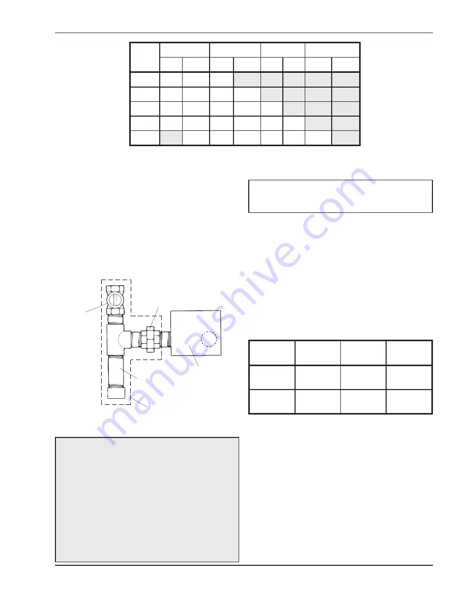
Gas  piping  must  have  a  sediment  trap  ahead  of  the
boiler gas controls, and a manual shut-off valve locat-
ed outside the jacket. All gas piping should be tested
after installation in accordance with local codes.

Model

No.

1/2 in. Pipe

3/4 in. Pipe

1 in. Pipe

1 1/4 in. Pipe

Nat.

Pro.

Nat.

Pro.

Nat. Pro.

Nat.

Pro.

0042

125

350

500

0066

60

160

175

460

0090

30

80

125

300

400

0135

15

40

60

150

200

450

0180

20

35

90

115

300

425

Table H: Maximum Equivalent Pipe Length (Feet)

Sediment Trap

(min. length 3”)

Union

Manual

Valve

Gas Valve

Must be supplied
by installer

Fig. 14: Sediment Trap

CAUTION:

The boiler and its manual shut-off valve

must  be  disconnected  from  the  gas  supply  during
any pressure testing of that system at test pressures
in  excess  of  1/2  psi  (3.45  kPa).  Dissipate  test
pressure in the gas supply line before reconnecting
the boiler and its manual shut-off valve to gas supply
line.  FAILURE  TO  FOLLOW  THIS  PROCEDURE
MAY  DAMAGE  THE  GAS  VALVE.  OVER
PRESSURED  GAS  VALVES ARE  NOT  COVERED
BY WARRANTY. The boiler and its gas connections
shall be leak tested before placing the appliance in
operation.  Use  soapy  water  for  leak  test.  DO  NOT
use open flame.

NOTE:

Do  not  use  teflon  tape  on  gas  line  pipe

thread. A flexible sealant suitable for use with Natural
and Propane gases is recommended.

These boilers are also certified to operate on propane
gas,  when  equipped  with  the  combination  gas  valve
and orifices (pilot and main burners) sized for propane
gas.

Gas Pressure

The gas valve is provided with pressure taps to meas-
ure  gas  pressure  upstream  of  the  gas  valve  and
downstream which is the same as the manifold pres-
sure.

Water Connections & System

Piping

The pipe size for water connections is shown on page
6. Typical piping systems are shown on page 17.

This  boiler  is  supplied  with  a  circulator  and  built-in
bypass  as  standard  to  ensure  the  required  minimum
water flow in the boiler. The bypass on models H-0135
and H-0180 is provided with an adjustable valve that is
factory-set  in  the  full  open  position.  The  handle  is

Gas Type

Inches

WC Min.

Inches

WC Max.

Regulator

Setting

Natural

7.0

10.5

3.5

Propane

12.0

13.0

11.0

Table I: Minimum and Maximum Gas Pressure

15

Содержание 0042B

Страница 1: ... in an explosion or fire WHAT TO DO IF YOU SMELL GAS Do not try to light any appliance Do not touch any electrical switch do not use any phone in your building Immediately call your gas supplier from a neighbor s phone Follow the gas supplier s instructions If you cannot reach your gas supplier call the fire department Installation and service must be performed by a qualified installer service age...

Страница 2: ...2 Rev 33 reflects the following Changes to Wiring Diagram for IID On Off on page 20 Wiring Diagram for IID 2 Stage on page 21 Additions None Deletions None ...

Страница 3: ...18 WIRING DIAGRAMS 20 SERvICING PROCEDURES 26 General Location of Controls 26 SEqUENCE OF OPERATION 26 Intermittent Ignition Device IID 26 START UP PROCEDURES 27 Lighting the Boiler 27 Filling the System 27 Checking the Circulator 27 Safety Information 27 Operating the Boiler 27 To Turn Off Gas to the Boiler 28 Shut down Procedure 28 Testing the Ignition Safety Shut off 29 Safe Shut down Tests 29 ...

Страница 4: ...s on which the heater will operate is the same type as that specified on the heater rating plate DANGER Failure to install the draft hood on indoor installations and properly vent the heater to the outdoors as outlined in the Venting section of this manual can result in unsafe operation of the heater To avoid the risk of fire explosion or asphyxiation from carbon monoxide never operate this heater...

Страница 5: ...est edition of the American National Standard ANSI Z21 13 CSA 4 9 Each boiler has been constructed and pressure tested in accordance with the requirements of Section IV of the American Society of Mechanical Engineers Code and factory fire tested These boilers are designed for indoor installation with a built in drafthood and a built in sub base for com bustible flooring Models are equipped with an...

Страница 6: ...H 0042 42 35 30 1 in 1 2 in 11 in 5 3 4 in 5 1 2 in 4 in H 0066 66 54 47 1 in 1 2 in 11 in 5 3 4 in 5 3 4 in 5 in H 0090 90 74 64 1 in 1 2 in 11 in 5 3 4 in 5 3 4 in 5 in H 0135 135 109 95 1 1 4 in 1 2 in 18 in 6 1 4 in 6 1 4 in 6 in H 0180 180 148 129 1 1 4 in 1 2 in 18 in 6 1 4 in 8 in 7 in Table A Specifications 6 ...

Страница 7: ...addition the boiler shall be installed such that the gas ignition system components are protected from water dripping spraying rain etc during appliance operation and service circulator replacement control replacement etc Clearance Requirements 1 Minimum clearances from combustible materials are listed in Table B below 2 A front clearance of at least 24 is recommended for adequate service of burne...

Страница 8: ... found in refrigerants aerosol propellants drycleaning fluids degreasers and paint removers Other harmful elements may come from bleaches air fresheners or mastics Vapors from these types of products can form corrosive acid compounds when burned in a gas flame The resulting acid condensate can damage or substantially reduce the life of the heater It may be necessary to provide outside air directly...

Страница 9: ...st terminate with a listed vent cap which complies with the local codes or in the absence of such codes to the latest edition of the National Fuel Gas Code ANSI Z223 1 The discharge opening must be a minimum of two 2 feet vertically from the roof surface and at least two 2 feet higher than any part of the building within eight 8 feet Vent stack shall be at least five 5 feet in vertical height abov...

Страница 10: ...Venting of Equipment section of the National Fuel Gas Code ANSI Z223 1 or applicable provisions of the local building codes Common vents Manifolds that connect more than one boiler to a com mon chimney must be sized to handle the combined load Consult available guides for proper sizing of the manifold and the chimney At no time should the area be less than the area of the largest outlet Fig 5 Mini...

Страница 11: ...been determined that each appliance remaining connected to the common venting sys tem properly vents when tested as outlined above return doors windows exhaust fans fireplace dampers and any other gas burning appliance to their previous conditions of use 7 Any improper operation of the common venting system should be corrected so that the installation conforms with the latest edition of the Nation...

Страница 12: ...t system as this will create a haz ardous condition Fig 9 Installing The Vent Damper in Horizontal Vertical Vents Fig 10 D80D General Wiring Diagram Install the vent damper to service only the single appliance for which it is intended If improperly installed a hazardous condition such as an explo sion or carbon monoxide poisoning could result vent Damper Operation For safe efficient operation the ...

Страница 13: ... main burners are operating Flair Damper NOTE To place vent damper in the open position to allow burner operation Turn the power off Turn the damper blade to fully open position arrow facing same direction as vent pipe Turn power on SS R2 SS2 ES R SC R1 M 2 3 4 1 JUMPER GV 24 VAC TR HL L L 1 2 120 VAC 60Hz TH 1 Fig 12 System Schematic Abbreviation Description M Damper Motor R Relay ES End Switch S...

Страница 14: ...VENT DAMPER 14 ...

Страница 15: ...LLOW THIS PROCEDURE MAY DAMAGE THE GAS VALVE OVER PRESSURED GAS VALVES ARE NOT COVERED BY WARRANTY The boiler and its gas connections shall be leak tested before placing the appliance in operation Use soapy water for leak test DO NOT use open flame NOTE Do not use teflon tape on gas line pipe thread A flexible sealant suitable for use with Natural and Propane gases is recommended These boilers are...

Страница 16: ...ns at the boiler to facilitate servicing The pressure relief valve is mounted on the boiler and must be piped to a drain We recommend that all high points be vented and that purge valves be installed A boiler installed above radiation level must be provided with a low water cutoff device The boiler when used in connection with a refrigera tion system must be installed so that the chilled medium is...

Страница 17: ...tlet sensor error While present operation ceases IND Call On Solid Turns on when IND Call short or 0 32 Vac is present Flashing System supply sensor error While present operation continues using boiler outlet sensor WWSD On Solid Turns on when in Outdoor Reset AND WWSD Active AND control in WWSD Flashing Outdoor sensor error While present operation continues with Fixed boiler target of 140 based o...

Страница 18: ... The Boiler Pump P1 is controlled by the boiler and is cycled off using a 5 minute fixed purge delay after burner operation has ceased The DIP switch settings are as follows DIP 1 ON ON OFF OFF 2 STAGE DIP 2 ON OUTDOOR RESET DIP 3 ON WWSD 70 F DIP 4 ON 190 F BOIL MAX DIP 5 ON HYDRONIC Hydronic with Outdoor Air Reset For hydronic operation with outdoor air reset the System Supply Sensor S2 is used ...

Страница 19: ...Fig 17 Multiple Zones with Circulators Fig 18 Multiple Zones with Circulators and Indirect DHW Tank 19 ...

Страница 20: ...Wiring Diagrams 20 ...

Страница 21: ...21 ...

Страница 22: ... PROVIDED BY OTHERS PROVIDED BY OTHERS Fig 19 Single Zone Taco Valve Fig 20 Dual Zone Taco Valve NOTE Maximum three 3 zone valves per one 1 40 VA transformer 22 ...

Страница 23: ... Zone Honeywell Valve NOTE Maximum five 5 zone valves per one 1 40 VA Transformer PROVIDED BY OTHERS Fig 22 System with Three 3 Zone Pumps NOTE Check VA rating of each relay coil Total load must not exceed VA rating of transformer 23 ...

Страница 24: ...Fig 23 Power Vent System with Zone Valve Taco 24 ...

Страница 25: ...25 Fig 23 Power Vent System with Zone Valve Honeywell ...

Страница 26: ... does not light the module will not energize the second main valve and the burners will not light Ignition spark continues only until the timed trial for ignition period ends Then the module goes into safe ty shutdown or lockout Lockout de energizes the first main valve operator and closes the first main pilot valve in the gas control stopping pilot gas flow The ignition control system must be res...

Страница 27: ... light the pilot by hand WARNING If you do not follow these instructions exactly a fire or explosion may result causing property damage personal injury or loss of life START UP PROCEDURES Lighting the Boiler Safe lighting and other performance criteria were met with the gas manifold and control assembly provided on the boiler when the boiler underwent tests specified in the latest edition of the A...

Страница 28: ...9 Honeywell Pilot Shut down Procedure To prevent freeze damage to the heating system it is recommended that the following system shut down procedure be performed 1 Set the room thermostat to OFF or the lowest setting 2 Turn off all electrical switches to the boiler 3 Turn off all gas valves supplying gas to the boiler Refer to operating instruction label on the boiler 4 Shut off the water supply t...

Страница 29: ...ould restart Inspection Procedures Burners Clean main burners and air louvers of dust lint and debris Keep boiler area clear and free from com bustibles and flammable liquids Do not obstruct the flow of combustion and ventilation air Make visual check of burner and pilot flame Yellow flame indicates clogging of air openings Lifting or blowing flame indi cates high gas pressure Low flame indicates ...

Страница 30: ...ean the tubes remove the heat exchanger ream tubes and immerse heat exchanger in non inhibited de scale solvent Heat Exchanger Removal 1 Shut water gas and electricity off close valves relieve pressure and remove relief valve Remove front inspection panel 2 Remove top holding screws 3 Remove draft diverter lift and remove top and flue collector on stack type models 4 Loosen bolts and disconnect fl...

Страница 31: ...uld be replaced with new ones 2 Install in out and return water headers and install header retainer nuts and torque nuts evenly 3 Replace V baffles 4 Install thermostat sensing bulbs in header wells and replace bulb retaining clips 5 Install inlet and return pipes in water headers using pipe thread sealant 6 Install water pressure relief valve flow switch and low water cut off devices if so equipp...

Страница 32: ...e to re install Gas valve Adjustment Robertshaw Invensys 7000 Series 2 Stage Gas valve with Solenoid valve 1 Turn the heater off 2 Remove the 3 8 nut or the 10 Torx screw 3 Lift solenoid valve up keeping the wires connect ed to the solenoid valve 4 If only low fire adjustment is needed go to Step 9 5 Using a 3 8 wrench carefully remove the alu minum cap that was under the solenoid valve count of t...

Страница 33: ... control cover screws and open control compartment 3 Disconnect wiring to the board 4 Carefully pull out the control board from the nylon pin supports Reverse above procedure to re install Fast Response Temperature Sensor Probe Replacement 1 Shut off electrical power to the boiler 2 Shut off water supply to the boiler and open drain valve to remove water to the sensor probe level 3 Remove control ...

Страница 34: ...ompletely filled in with the heater serial number model number etc and shipped to Raypak freight prepaid If determined defective by Raypak and within warran ty the part will be returned in kind or equal substitution freight collect Credit will not be issued RAYPAK INC 2151 Eastman Avenue Oxnard CA 93030 NOTE To supply the correct part it is important that you supply the model number serial number ...

Страница 35: ...this Warranty Raypak will furnish a replacement for any failed part The failed part must first be returned to Raypak if requested with transportation charges prepaid and all applicable warranty conditions satisfied The replacement part will be warranted for only the unexpired portion of the original warranty Raypak makes no warranty whatsoever on parts manufactured by others but Raypak will apply ...

Страница 36: ...36 www raypak com Raypak Inc 2151 Eastman Avenue Oxnard CA 93030 805 278 5300 Fax 805 278 5468 Litho in U S A ...

Отзывы: