

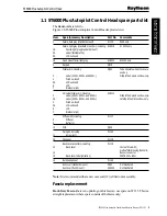


ST6000 Plus Autopilot Control Head
Z299,
A12022,
E12025
2
ST6000 Plus Autopilot Control Head Service Manual 83117-1
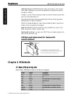
Chapter 1. Disassembly/Assembly
1. Fascia (dark grey)
1A.
Fascia (light grey)
1B. Flush mount fascia (light grey)
2. Keypad
3. Label (old profile)
3A. Label (latest profile)
4. Window insert
5. LCD surround
5A.
LCD surround
6. LCD
7. Elastomer strip (x2)
D4586-1
2
17 (Note A)
1
3 (Note D)
5 (Note D)
6
7 (x2)
8 (Note B)
9
10
12 (Note C)
11 (x3)
Torque to
0.33 Nm
(3 lb in)
14
13
11 (x8)
Torque to
0.33 Nm
(3 lb in)
15
16
Notes:
A. Earlier production units have a shim (17) fitted to
aid keypad compression.
B. The castellated top edge of the diffuser (8) fits under
the legs of the LEDs on the top edge ofthe PCB (10).
C. It is recommended that a new case seal (12) is fitted
on reassembly.
D. Only fitted on units with CURVED window to fascia.
4 (Note D)
1B
E12025,
Light Grey Flush Mount Control Head
1A
Fascia with curved window
Pips
Horizontal rib
Fascia with flat window
5A
3A
2
8. Diffuser
9. Reflector
10. PCB
11. Retaining screw (x1
1)
12. Case seal
13. Rear cover
14. Buzzer connector
15. Back cover label ()
16. Bulkhead gasket
17. Keypad shim (earlier units only)
Figure 1: ST6000 Plus Autopilot Control Head exploded view


