background image


Raytheon Anschuetz GmbH 
Postfach 11 66 
D-24100 Kiel 
Germany 
Tel +49-4 31-30 19-0 
Fax +49-4 31-30 19 464 
Email [email protected] 
www.raytheon-anschuetz.com 


Edition: February 2020 

4352.DOC010002 


Operator Unit 130-626.NG002 
 
Standard 22 GYRO COMPASS 

Operator and Service Manual 


Содержание 130-626

Страница 1: ... 66 D 24100 Kiel Germany Tel 49 4 31 30 19 0 Fax 49 4 31 30 19 464 Email service raykiel com www raytheon anschuetz com Edition February 2020 4352 DOC010002 Operator Unit 130 626 NG002 Standard 22 GYRO COMPASS Operator and Service Manual ...

Страница 2: ...tattet Zuwiderhandlungen verpflichten zu Schadenersatz Änderungen dieses Dokuments und dessen Inhalt bleiben vorbehalten This document and its content are copyright protected Distribution reproduction and storage as well as translation and exploitation of this document and its content in whole or in parts and regardless of what form are prohibited without prior express written permission Offenders...

Страница 3: ...oughly If you have any further questions please contact us on the following address RAYTHEON ANSCHÜTZ GMBH Zeyestr 16 24 D 24106 Kiel Germany Tel 49 431 3019 0 Fax 49 431 3019 291 All rights reserved No part of this manual may be copied neither mechanically electronically magnetically manually nor otherwise or distributed forwarded or stored in a data bank without written permission of RAYTHEON AN...

Страница 4: ...le with software version E00 03 E00 04 E01 01 E01 02 E00 05 E00 06 added Graphical ROT roll and pitch indication chapter 1 4 4 Latitude input with north south indication required for systems with Standard 30 MF Interface for gyro compass system remote control chapter 1 8 Magnetic heading automatic variation correction by use of RMC telegram Threshold for heading monitoring extended to 50 ...

Страница 5: ...ing 1 10 1 4 2 2 Speed Error Correction 1 12 1 4 2 3 DV Bus 1 14 1 4 2 4 Speed Source DU 1 15 1 4 2 5 Heading Uncorrected 1 16 1 4 2 6 Rate of Turn 1 17 1 4 2 7 Deviation Table 1 18 1 4 2 8 Gyro Data 1 19 1 4 2 9 CAN Devices 1 20 1 4 2 10 Software Versions 1 22 1 4 3 Heading and RoT 1 23 1 4 4 RoT Roll Pitch 1 24 1 4 5 Alerts 1 24 1 5 Dimming 1 26 1 6 CAN Bus 1 27 1 7 Bridge Alert Management BAM 1...

Страница 6: ...2 9 4 Change Speed Source DU 2 20 2 9 5 Deviation Table 2 21 2 9 5 1 Deviation Tables in a GG R System 2 21 2 9 6 Select Damping of Rate of Turn 2 22 2 9 7 Set Speed Error Correction 2 22 2 10 Activate Quick Settling 2 24 2 11 Lamp Test 2 27 3 Installation 3 1 3 1 Safety Information 3 1 3 2 Installation 3 2 3 3 Connection 3 2 3 3 1 Connect Supply Voltage at Plug B9 3 5 3 3 2 Connect CAN Bus at Plu...

Страница 7: ...10 Heading Uncorrected 1 16 Figure 1 11 Rate of Turn 1 17 Figure 1 12 Deviation Table 1 18 Figure 1 13 Gyro Data 1 19 Figure 1 14 CAN Device 1 20 Figure 1 15 Software Versions Figure may vary from actual Device 1 22 Figure 1 16 Heading 1 23 Figure 1 17 RoT Roll and Pitch 1 24 Figure 1 18 Alerts Unacknowledged 1 25 Figure 1 19 Block Diagram CAN Bus 1 27 Figure 1 20 No CAN Connection 1 31 Figure 2 1...

Страница 8: ...Elements at the Connection Board 3 14 Figure 3 11 Definition of NMEA Telegram PANZHDS 3 20 Figure 3 12 Definition of NMEA Telegram PANZSLD 3 21 Figure 3 13 Definition of NMEA Telegram PANZDAT 3 21 Figure 4 1 Alert Message 4 2 TABLE OF TABLES Table 1 1 Speed Source DU 1 15 Table 1 2 Gyro Data 1 19 Table 1 3 Alert List Alarm Symbols 1 29 Table 1 4 Alert List Warning Symbols 1 30 Table 1 5 Alert List...

Страница 9: ...ls are used in this manual WARNING Warning statements indicate a hazardous situation that if not avoided could result in death or serious injury CAUTION Caution statements indicate a hazardous situation that if not avoided could result in minor or moderate injury or equipment damage Notes indicate information considered important but not hazard related ...

Страница 10: ...ipment and systems Digital interfaces 0 3 List of Abbreviation Term Description BAM Bridge Alert Management BNWAS Bridge Navigational Watch Alarm System CAM HMI Central Alert Management Human Machine Interface CAN Controller Area Network DP System Dynamic Positioning System GG R Gyro Gyro Magnetic Redundancy IMO International Maritime Organization MC Magnetic Compass RoT Rate of Turn SEC Speed Err...

Страница 11: ...evices non Raytheon devices connected to the distribution unit are not output via the operator unit Only a sensor error would be reported by a timeout CAUTION If there are more than one operator unit in an application than all settings and configurations have to be performed for each operator unit CAUTION After configuration changes the distribution unit and the operator unit must be reset Changes...

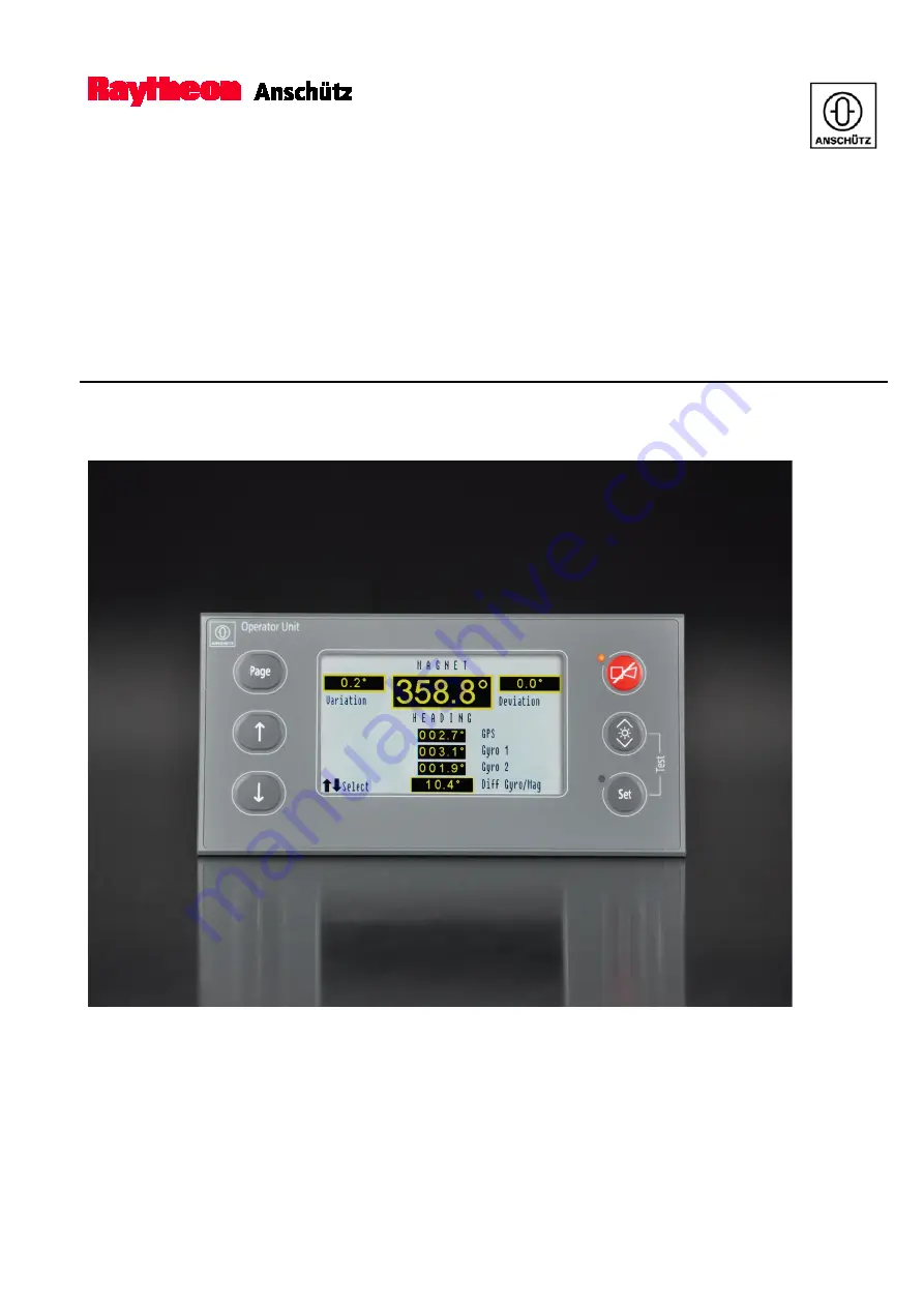
Страница 12: ...possible to connect more than one operator unit to the CAN Bus Both operator units connected to the system have the same priority Figure 1 1 Operator Unit Desk Flush Mounted The operator Unit is available in 2 versions desk flush mounted and with angled fixing bracket The operator unit consists of Front Panel with 6 buttons 2 LEDs 2 PCBs a transmitter for audible alarms mounted behind the front pa...

Страница 13: ...ilable Figure 1 2 Operating Elements and Indicators Gyro Compass Selected Pos No Designation Function 1 Select Down Use the Select Down button to navigate through the display 2 Select Up Use the Select Up button to navigate through the display 3 Page Use the Page button to navigate through the main pages or to get back to the overview page 4 Speed Displays the speed 5 Selected Sensor Displays the ...

Страница 14: ... LED Flashes whenever an adjustment can be performed 11 Set Use the Set button to confirm the selection adjustment 12 Unselected sensors Displays the heading of the unselected sensors 13 Selection possible Appears on the display whenever a selection is possible Use select buttons 1 and 2 to navigate through the display Figure 1 3 Operating Elements and Indicators Magnetic Compass Selected Pos No D...

Страница 15: ... distribution units via the CAN Bus Make sure that the receivers are allowed to use the heading information from a magnetic compass 1 4 Main Pages The operator unit provides 4 main pages which can be selected with the Page button Figure 1 2 3 Overview Heading Difference Service Difference Alarm for Gyro Gyro and Gyro Magnetic Auto Heading Spd Err Corr DV Bus activated Speed Source DU Heading uncor...

Страница 16: ...ng information Speed The last selected mode is selected by default The following modes are available Automatic Speed Aut Speed Manual Speed Man Speed Individual Speed Ind Speed To switchover to Man Speed see chapter 2 7 2 For information about Individual Speed see chapter 1 4 2 2 Latitude The last selected mode is selected by default The following modes are available Automatic Latitude Aut Latitud...

Страница 17: ...oring Service Heading Monitoring Within the compass system all connected heading sensors are compared with each other in order to monitor and display the difference of a defined threshold If the sensor difference is greater than the user threshold value an alert Heading Difference Gyro Gyro GPS or Heading Difference Gyro GPS Magnetic is displayed and has to be acknowledged see chapter 4 2 Figure 1...

Страница 18: ... February 2020 Gyro compass can be Compass Standard 22 Standard 30 MF or other external non Raytheon Anschütz heading devices Magnetic compass can be Raytheon Anschütz magnetic probe or other non Raytheon Anschütz magnetic compasses For setting the threshold value see chapter 2 8 ...

Страница 19: ...ec The service page shows the heading of the selected sensor see Figure 1 5 To open the service mode and the sub menus of the service page see chapter 2 9 1 Every sub menu of the service page except from the deviation table has a timeout function Opening a sub menu the timeout function starts with 120 seconds The remaining time is displayed on the left hand side of the display If nothing is change...

Страница 20: ...e 1 2 1 and 2 to navigate through the display 2 Remaining Time Shows the remaining time until it switches back to the overview page 3 Back Switches back to the previous page 4 Set Value Confirm the settings for auto heading 5 Gyro Selection Decide if an automatic switch over to the gyro compass GPS THD compass es is desired 6 TMC Selection Decide if an automatic switch over to the magnetic compass...

Страница 21: ...as to be performed manually For changing the current sensor see chapter 2 7 To change the settings for auto heading see chapter 2 9 2 If an automatic switchover takes place the alert Autom Switched to XXX is displayed and has to be acknowledged see chapter 4 2 There is no message in case of a manual switch over XXX can be Gyro GPS THD or Mag ...

Страница 22: ...yro compass systems 1 Manual input of speed and latitude In this application speed and latitude are manually input via the Operator Unit of the gyro compass This data is transferred to all connected Standard 22 gyro compasses Thus all Standard 22 gyro compasses calculate the speed error with the same data It is obligatory to input actual speed and latitude data in order to ensure a correct speed e...

Страница 23: ... 22 no 2 accordingly for speed In this application faulty speed or latitude data affect the heading of only one Standard 22 Advantage Heading monitoring systems or subsequent systems such as DP systems are able to detect heading errors between 2 or more Standard 22 caused by wrong speed or latitude data For dual or triple Standard 22 or Standard 30 MF gyro compass systems not used in combination w...

Страница 24: ... Chapter is for information only This sub menu provides the opportunity to connect a DV Bus to the distribution unit 138 118 and to assign a DV Bus address For a detailed description see manual of the Distribution Unit 138 118 The address of the distribution unit must only be assigned once in the DV Bus system Figure 1 8 DV Bus To connect the DV Bus and to set the address see chapter 2 9 3 ...

Страница 25: ...use the speed sensor is not connected to the distribution unit display information by selecting this menu is Not accepted The same happens if no external speed sensor is connected Figure 1 9 Speed Source DU Table 1 1 Speed Source DU Display Description Puls Log VHW Water speed and heading VTG Course over ground and ground speed VBW Wtr Water speed VBW Gnd Ground speed selected Connected and select...

Страница 26: ...tion from the gyro compass and the magnetic compass is displayed Correction values of the gyro compass are speed error correction Correction values of the magnetic compass are variation and deviation Uncorrected heading values from external third party devices which are connected via a distribution unit cannot be displayed Figure 1 10 Heading Uncorrected ...

Страница 27: ...in the distribution unit type 138 118 Figure 1 11 Rate of Turn A positive sign and a green bar stand for a rate of turn to starboard A negative sign and a red bar stand for a rate of turn to port side Damp 0 small damping 0 s Damp 1 middle damping 5 s Damp 2 strong damping 10 s To select the damping see chapter 2 9 6 CAUTION If there is no Rate of Turn indicator connected in the respective applica...

Страница 28: ...eviates With correction values deviation values the deviation fault can be corrected This correction value is entered via the operation unit to the distribution unit and is used to correct the magnetic heading information The deviation table provides correction values which can be set changed or erased Variation and deviation are used to determine the True Magnetic Heading and must be checked and ...

Страница 29: ...upply Supply voltage of the gyro sphere Gyro current Current consumption of the gyro sphere Pump supply Supply voltage of the pump Pump current Current consumption of the pump Sensor PCB Status of Sensor PCB Ok no error message of the sensor PCB Failure Error at sensor PCB Power PCB Status of Power PCB Ok no error message of the power PCB Failure Error at power PCB Gyro PCB Status of Gyro PCB Ok n...

Страница 30: ...The CAN Devices sub menu displays the Unit ID and the CAN Bus status of all devices connected to the CAN Bus Figure 1 14 CAN Device Pos No Designation 1 Unit ID 2 Connected Device 3 CAN Bus Status The first column displays the Unit ID the second column the connected device and the third column the CAN Bus status Following devices can be shown OU Operator Unit GY Gyro Compass DU Distribution Unit R...

Страница 31: ... GYRO COMPASS Edition February 2020 1 21 4352 DOC010002 First digit 1 CAN Bus Second digit 2 CAN Bus Following CAN Bus statuses are possible 0 No Timeout 1 Timeout 2 unknown device itself For example 01 1 CAN Bus No timeout 2 CAN Bus Timeout ...

Страница 32: ...Unit P01 Program at the sensor PCB P02 Program at the power PCB P03 Program for MC 1 at the outer sphere PCB P04 Program for MC 1 at the outer sphere PCB P05 Program of the CAN Bus processor DV Bus at the interface PCB P06 Program of the I O PCB processor P07 Program at the I O PCB Exx Software Version Sensor not able to send software 2 Remaining Time Shows the remaining time until it switches bac...

Страница 33: ...sor is displayed to provide the possibility to read the heading information from a greater distance Figure 1 16 Heading Pos No Designation Function 1 Heading Shows the heading of the selected sensor 2 Tendency Bar Displays the Rate of Turn value in the tendency bar 3 RoT Value Displays the Rate of Turn value A positive sign and a green bar stand for a rate of turn to starboard A negative sign and ...

Страница 34: ... Pitch Tendency Bar Displays the Pitch value in the tendency bar 6 Pitch Value Displays the Pitch value A positive sign and a green bar stand for a rate of turn or roll to starboard and a pitch forward A negative sign and a red bar stand for a rate of turn or roll to port and a pitch aft 1 4 5 Alerts The display changes to the alert page and generates an acoustic signal when an alert occurs The st...

Страница 35: ...o Designation Function 1 State Shows the priority of the alerts For detailed information see chapter 1 7 2 Alert Text Shows the device and the Unit ID and the alert message see Figure 4 1 For detailed information of the alert messages see chapter 4 2 3 Changed Shows the time of acknowledgement 4 Total Amount of alerts in total 1 2 3 4 ...

Страница 36: ...g on the configuration see configuration tool The operator unit can also act as a central dimmer meaning that other devices of NautoSteer AS follow the dimming value of the operator unit Precondition for this function is that the receiver and the transmitter of the telegram are assigned to the same group For details of the dimming operation see chapter 2 4 ...

Страница 37: ... 16 is reserved for development purposes Each bus user can send and receive data via the CAN Bus The CAN Bus must be terminated at both ends via an ohmic resistor This terminating resistor is set by jumpers switches or cable bridges on the respective PCB A redundant CAN Bus is provided CAN1 and CAN2 The maximum length of a CAN Bus cabling must not be longer than 400 meter Gyro Compass Gyro Compass...

Страница 38: ...t reduces the cognitive workload of the operator by minimizing the information presented which is necessary to draw attention to and to assess the situation On the bridge alerts are presented on the individual equipment and or on a central alert management human machine interface CAM HMI Alerts are divided in different priorities Emergency alarm Highest priority of an alert Alarms which indicate i...

Страница 39: ... at the task station Category B Alerts where no additional information for decision support is necessary besides the information which can be presented at the CAM HMI These alerts can be acknowledged at the task station or at the CAM HMI Category C Alerts that cannot be acknowledged on the bridge but for which information is required about the status and treatment of the alerts e g certain alerts ...

Страница 40: ...ning flashing Table 1 5 Alert List Caution Symbol Icon Symbol Description Caution Table 1 6 Alert Signaling Colour Meaning Visual Acoustic Signals Red Alarm flashing Alarms faults and or dangerous situations Three short signals pulses every 7 seconds Continues until acknowledgment Yellowish orange warning flashing Warnings Two short signals pulses after the event without repetition Yellow Caution ...

Страница 41: ...at are used for speed error correction mode of speed error correction Thresholds for heading monitoring gyro gyro and gyro TMC The compass system is able to receive the following data from INS Number of selected heading sensor Thresholds for heading monitoring gyro gyro and gyro magnetic For the communication a bidirectional RS422 connection with proprietary NMEA telegrams PANZxxx can be used For ...

Страница 42: ...192 mm Depth 82 mm Weight 1 5 kg Type of Enclosure IP23 back side IP56 front side see Dimensional Drawing 130 626 HP005 higher rating with special casing 1 10 2 Electrical Data Supply Voltage 24 V DC 18 36 V DC galvanically isolated Power Consumption 6 W Interfaces 2 x CAN Bus Serial interface for BAM in accordance to IEC 61162 1 2 IEC 61924 2 Relay contact for BNWAS ...

Страница 43: ...02 2 Operation 2 1 Safety Information CAUTION After changes in the configuration of the Speed Error Correction and DV Bus service page the distribution units and the operation units have to be reset Changes have to be performed to all distribution units and operator units in a compass system ...

Страница 44: ...minutes after switching on heating stage it is possible to activate the quick settling function see chapter 2 9 6 The switching on process is divided in the following stages May vary depending on the connected gyro system Heating stage Settling stage Heating Stage During the heating stage of the gyro system the heading information is not valid which is indicated by a set of dashes The heating stag...

Страница 45: ...xtent The gyro system is settled after a period of 4 hours for Raytheon Anschütz Standard 22 Until then the heading information has a reduced accuracy The settling stage is displayed below the heading information see Figure 2 2 If a second gyro is connected the settling stage is indicated with settling next to heading information of the unselected gyro Figure 2 2 Settling Stage ...

Страница 46: ... to navigate through the main pages or to get back to the overview page 4 Speed Displays the speed 5 Selected Sensor Displays the heading of the selected sensor 6 Latitude Displays the latitude 7 Alert LED Flashes red when a new alert occurs illuminates continuously when the alert is acknowledged but not eliminated 8 Acknowledge Use the Acknowledge button to open the alert page only possible if al...

Страница 47: ...gure 2 3 3 to navigate through the 4 main pages 2 3 2 General Settings Change the values Use the Select buttons to navigate through the display and to change values In the left corner of the display a selection symbol see Figure 2 4 is indicated whenever a selection is possible Figure 2 4 Selection Symbol Confirm the setting Use the Set button to confirm settings In the right corner of the display...

Страница 48: ...ightness button again to decrease The brightness decreases as long as the button is pressed The first operation of the button always increases the brightness 2 5 Switchover between Day Mode and Night Mode The display colours can be changed It can be switched between day mode and night mode A switchover from day mode to night mode is not possible if the alert page is displayed if the Set LED flashe...

Страница 49: ...elonging to the same group has been switched over No The display mode can only be changed at this device Changes of connected devices do not affect this device 2 Display Mode Displays the current previewed colour mode 3 Day Displays the current activated day mode for switch over between day mode and night mode 4 Night Displays the current activated night mode for switch over between day mode and n...

Страница 50: ...button Figure 2 3 11 The Night mode is highlighted 6 Use the Select buttons Figure 2 3 1 and 2 to change the night mode The Display Mode shows the currently previewed mode 7 Confirm the selection of the night mode with the Set button Figure 2 3 11 The following colour modes are available Day 1 Bright on white background Day 2 Dark on white background Day 3 Bright on blue background Night 1 Fluores...

Страница 51: ...d to use magnetic heading After switching on the operator unit GYRO 1 is selected as the default compass and the heading value is displayed All other connected and displayed heading sensors can be selected 1 Open the overview page 2 Use the Select buttons Figure 2 3 1 and 2 to select a sensor 3 Press the Set button Figure 2 3 11 to confirm the selection The selected sensor will be displayed in the...

Страница 52: ...itude CAUTION It is recommended to read the information about Individual SEC first before the function Individual Lat is applied 1 Open the overview page see chapter 2 3 1 2 Select Latitude with the Select buttons Figure 2 3 1 and 2 3 Press the Set button Figure 2 3 11 to confirm the selection 4 Use the Select buttons Figure 2 3 1 and 2 to switch between Aut Latitude Ind Latitude and Man Latitude ...

Страница 53: ...page see chapter 2 3 1 2 Select Variation with the Select buttons Figure 2 3 1 and 2 3 Press the Set button Figure 2 3 11 to confirm the selection 4 Use the Select buttons Figure 2 3 1 and 2 to switch the value The changed value is displayed italic 5 Press the Set button to confirm the value After confirmation the values are saved in an internal table so the magnet compass heading is corrected acc...

Страница 54: ... value for the difference between gyro and magnetic 2 Diff G G Shows and enables the setting of the user threshold value for the difference between gyro and gyro Set the threshold value for the difference alarm 1 Open the Heading Difference Page 2 Select the threshold value to be changed Figure 2 7 1 or 2 with the Select buttons 3 Press the Set button Figure 2 3 11 to confirm the selection 4 Use t...

Страница 55: ... Difference Set Switch Over Auto Heading DV Bus Settings Change Speed Source DU Deviation Table Select Damping Set Speed Error Correction 2 9 1 Open the Service Mode If nothing is changed and no sub menu is selected the service page switches back to the overview page after approx 10 sec 1 Press the Page button Figure 2 3 3 and navigate to the heading difference service page 2 Use the Select button...

Страница 56: ...ruary 2020 Figure 2 8 Open the Service Mode 3 Press the Select Down button Figure 2 3 1 for approx 3 sec to enter the service mode The service mode is activated 4 Press the Up or Down button Figure 2 3 3 to navigate through the sub menus see Figure 2 9 Figure 2 9 Service Mode Sub Menus ...

Страница 57: ...Figure 2 10 Set Switchover Auto Heading Pos No Designation Function 1 Back Switches back to the previous page 2 Set Value Confirm the settings for auto heading 3 Gyro Selection Decide if an automatic switch over to the gyro compass GPS THD compass is desired 4 TMC Selection Decide if an automatic switch over to the magnetic compass is desired 1 Open the sub menu Auto Heading from the service page ...

Страница 58: ...er enabled No Automatic Switch over disabled 4 Press the Set button to leave the option 5 Use the Set button to set the value and leave the sub menu 1 Set the value Select Set the value Figure 2 10 2 and press the Set button to confirm 2 Leave the sub menu Select Back Figure 2 10 1 and press the Set button to confirm To leave the auto heading sub menu without any changes press the Page button ...

Страница 59: ...nection to the Distribution Unit is desired 4 Address Assign a DV Bus address 2 9 3 1 Connect DV Bus CAUTION After changes in the configuration of the DV Bus service page the operator units has to be reset DV Bus applications are not released for the use with Operator Unit 130 626 This Chapter is for information only 1 Open the sub menu DV Bus from the service page see chapter 2 9 1 The sub menu D...

Страница 60: ...s DV Bus enabled No DV Bus disabled 4 Use the Set button to set the value and leave the sub menu 1 Set the value Select Set the value and press the Set button to confirm If values have been changed the Operator Unit requires a restart 2 Leave the sub menu Select Back and press the Set button to confirm To leave the DV Bus sub menu without any changes press the Page button ...

Страница 61: ... 1 and 15 is possible 1 Open the sub menu DV Bus from the service page see chapter 2 9 1 The sub menu DV Bus opens see Figure 2 11 2 Use the Set button Figure 2 3 11 to navigate to Address Figure 2 11 3 3 Press the Select buttons Figure 2 3 1 and 2 to change the address 4 Use the Set button to set the value and leave the sub menu 1 Set the value Select Set the value and press the Set button to con...

Страница 62: ...of Individual Speed the speed source must be adjusted by DIP Switches at the gyro compass itself Figure 2 12 Speed Source DU Table 2 2 Speed Source DU Display Description Puls Log VHW Water speed and heading VTG Course over ground and ground speed VBW Wtr Water speed VBW Gnd Ground speed selected Connected and selected available Connected but not selected not available Possible but currently not c...

Страница 63: ...to navigate through the options 1 Edit value and set value A correction value can be edited and or set 2 Erase value Erases a selected value 3 Erase all values Erases all correction values of the deviation table If this option is selected the safety question Are you sure has to be confirmed with the Set button 4 Back Switches back to the previous page 3 Press the Set button Figure 2 3 11 to confir...

Страница 64: ...ution unit 138 118 is connected The damping of the RoT is not possible if the distribution unit 138 126 is connected 1 Open the sub menu Rate of Turn from the service page see chapter 2 9 1 The sub menu Individual Rate of Turn opens 2 Use the Select buttons Figure 2 3 1 and 2 to navigate through the options 3 Use the Set button to select a damping mode 2 9 7 Set Speed Error Correction 1 Select the...

Страница 65: ...ues are not available for speed error correction only the manual and individual values are available 6 Use the Set button Figure 2 3 11 to go to the option Individual 7 Change the option to Yes or No with the Select buttons Figure 2 3 1 and 2 Yes The Individual values are available for speed error correction No The Individual values are not available for speed error correction only the manual or t...

Страница 66: ...ick settling function can only be used if the ship s heading has not been changed between switching off and switching back on The quick settling function cannot be used For first setting into operation If the ship s position has been changed between switching off and switching on again If the temperature of the gyro supporting liquid is more than 30 C Within the first 3 minutes after switching on ...

Страница 67: ...ompass If several max 3 gyro compasses should be activated with the quick settling function it is recommended to switch on the compasses one after another in order not to exceed the three minutes After switching on the selected gyro compass quick settling is possible Figure 2 16 QS Possible 1 When QS possib is displayed see Figure 2 16 select the Page button Figure 2 17 Quick Settling Safety Quest...

Страница 68: ... which are available for quick settling are listed see Figure 2 18 Figure 2 18 Quick Settling Available Gyros Listed 3 Select the gyro compass to be quick settled with select buttons 4 Press the set button to confirm the selection Confirmation is shown on the display see Figure 2 19 Figure 2 19 Quick Settling Set ...

Страница 69: ...mp test during an alert is not possible Alerts are not displayed during a lamp test Figure 2 20 Lamp Test Pos No Designation 1 Brightness 2 Set 1 Press the brightness button Figure 2 20 1 and the set button Figure 2 20 1 simultaneously for approx 3 sec The LEDs light up and an acoustic alarm occurs 2 Follow the instructions on the display to check the functionality The software version is shown at...

Страница 70: ......

Страница 71: ...ed refer to Dimensional Drawing 130 626 HP005 WARNING When establishing cable connections ensure that the cables are disconnected from any power supply It is essential to ensure that all cables are disconnected from the power supply if necessary measure the voltage beforehand and or disconnect the relevant distributor WARNING While connecting cables to the equipment do not bend cables to acute ang...

Страница 72: ...011 NG002 E01 The operator unit must be configured before setting into operation This configuration can be performed with the Configuration Tool AS only Voltage supply and connections as well as the bus terminations must be performed according to the following sections For connecting the cables see also respective system wiring diagrams part of delivery for a complete CAN Bus system Do not forget ...

Страница 73: ...70 mm Be careful not to damage the screening 2 Trim the screening until approx 15 mm is on the cable Figure 3 1 Strip off the Cable Connection The cable length to strip off must be adapted to the length between the clamp and the terminals 3 Insert the cable ends into the terminal strip and tighten the terminal screws 4 Clamp the cable shield by fastening the suitable shielding clamp in the slits o...

Страница 74: ...dition February 2020 Shrinking sleeves must be used However do not strip the shrinking sleeve over the screening Figure 3 2 Proper Cable Connection Example Only It is recommended to fasten the connected cables with tie wraps to the housing of the operator unit see Figure 3 2 ...

Страница 75: ...eparate power switch When establishing cable connections ensure that the cables are disconnected from any power supply It is essential to ensure that all cables are disconnected from the power supply if necessary measure the voltage beforehand and or disconnect the relevant distributor Figure 3 3 Connect Supply Voltage at Plug B9 Table 3 1 Connect Supply Voltage at Plug B9 Plug terminal Function B...

Страница 76: ... B7 and B8 The termination of the CAN Bus depends on its application within a compass system Figure 3 4 Connect CAN Bus at Plugs B7 and B8 Table 3 2 Connect CAN Bus at Plugs B7 and B8 Plug terminal Remarks B7 1 B8 1 CAN Termination jumper between terminal 1 and 2 B7 2 B8 2 CAN Low L B7 3 B8 3 CAN High H B7 4 B8 4 CAN Ground ...

Страница 77: ...0 3 7 4352 DOC010002 3 3 3 Connect Status Output System Failure at Plug B4 Figure 3 5 Connect Status Output SYSTEM FAILURE at plug B4 Table 3 3 Connect Status Output SYSTEM FAILURE at plug B4 Plug terminal Remarks B4 1 B4 3 B4 2 The above shown status displays an error mode ...

Страница 78: ...ug B5 Figure 3 6 Connect Serial In and Serial Out at Plug B5 Table 3 4 Connect Serial In and Serial Out at Plug B5 Plug terminal Remarks RS422 RS485 B5 1 TX B B5 2 TX A B5 3 Ground Ground B5 4 RX N C B5 5 RX N C Observe the termination switches B1 RS422 Out and B2 RS422 IN Observe the switch position of B14 B17 and B16 for RS485 operation ...

Страница 79: ...nnect Relay Switching Outputs 1 to 4 at Plugs B6 and B11 Table 3 5 Connect Relay Switching Outputs 1 to 4 at Plugs B6 and B11 Plug terminal Remarks B6 1 B11 1 B6 3 B11 3 B6 2 B11 2 B6 4 B11 4 B6 6 B11 6 B6 5 B11 5 The above shown status displays the error free BNWAS case For detailed information about BNWAS see chapter 4 3 B6 Output 1 B11 Output 3 B6 Output 2 B11 Output 4 ...

Страница 80: ... 6 Connect the Digital Inputs 1 and 2 at Plug B10 Figure 3 8 Connect the Digital Inputs 1 and 2 at Plug B10 Table 3 6 Connect the Digital Inputs 1 and 2 at Plug B10 Plug terminal Remarks B10 1 B10 3 Digital in B10 2 B10 4 Digital in Terminals 1 and 2 for Digital in1 terminals 3 and 4 for Digital in2 ...

Страница 81: ...or serial in and serial out Baud rate for serial in and serial out Heartbeat telegram on off Type of alert communication ALR ACK or ALF ALC ACN ACR Serial interface alert and or remote A special configuration Tool type NB42 232 is necessary to configure the Operator Unit The use of this Configuration Tool is allowed only for Raytheon service personnel The adjustments switches B11 B1 B2 B12 B14 B16...

Страница 82: ...Elements of the CPU PC Board and the Connection PC Board Figure 3 9 Operation and Display Elements of the CPU PC Board Pos No Designation Function 1 DIP Switch B11 Development only 2 Push button B7 Push button RESET to reset the microcontroller 3 Push button B10 LED H11 LED H14 Push button SET with illumination LEDs white ...

Страница 83: ...ge 6 Push button B8 LED H8 LED H12 Push button ACK with illumination LEDs white 7 LED H7 LED ALERT red or green red means flashing An alert is active and must be acknowledged constant An already acknowledged alert is still present green currently not used 8 Push button B2 LED H1 LED H4 Push button Page with illumination LEDs white 9 Push button B3 LED H2 LED H5 Push button Scroll up with illuminat...

Страница 84: ...ard Pos No Designation Function 1 Plug B4 Relay Output System Failure Interactive relay system fail Active relay operation okay 2 Plug B9 24V DC supply voltage input 3 LED H1 Lights up red if System Fail is active 4 Switch B1 Is used to terminate RS422 Out or RS485 at plug B5 5 LED H2 Flashes green if there is a data transmission via Serial Input at plug B5 ...

Страница 85: ...Relay Switching Output 2 Out 1 Alert to BNWAS Out 2 Currently not used 12 Plug B11 Relay Switching Output 3 and Relay Switching Output 4 Out 3 4 Currently not used 13 LED H5 Lights up green if Relay Switching Output 2 is active 14 LED H11 Lights up green if Relay Switching Output 4 is active 15 Plug B7 CAN1 of the Dual CAN Bus 16 LED H6 Flashes green if there is a data transmission via plug B 7 17...

Страница 86: ...B17 Must be used in simultaneously only If they are switched the input SIN1 serial in RS422 is switched off and the output terminals of plug B5 for RS422 Out are used for data in out for a RS485 interface For Bridge Alert Management BAM Set the gyro Operator Unit to RS422 30 Switch B16 31 Switch B14 32 LED H9 Lights up green if a digital input bridges the terminals 3 and 4 of plug B10 33 Plug B10 ...

Страница 87: ...ommunication at the same time But to ensure the correct repetition rates it is recommended to use the interface only for Alert or Remote communication The following telegrams can be used for receiving data Interface Possible Telegrams Repetition Rate Acknowledge Alarm ACK Only once to acknowledge an alert Alert Command ACN Only once to acknowledge an alert Date Time for the Alerts ZDA1 1 s recomme...

Страница 88: ...Rate Set Alarm State ALR 1 s Alert Sentence ALF In the event of changes or on demand Cyclic Alert List ALC 20 s or in the event of changes Alert Command Refused ACR Answer to ACN if request was refused Heartbeat Supervision Sentence HBT 5 s All headings and selected sources PANZHDS 1Hz 38400Bd or 10Hz 38400Bd Speed and latitude data PANZSLD 5 s Heading difference alert thresholds PANZDAT 5 s ...

Страница 89: ...aud rates can be used 4800 Bd 9600 Bd 19200 Bd 38400 Bd Only the baud rates 4800 and 38400 are conform to IEC 61162 Select the following connection settings Data bit 8 Parity no Stop bit 1 The Operator Unit accepts all talker IDs but can only transmit HE For information about the BNWAS interface see chapter 4 3 ...

Страница 90: ... heading fields can be empty NULL if the sensor does not exist The selected sensor field must not be empty In total 4 sensors are allowed e g 3 Gyro TMC or 2 Gyro GPS THD TMC This telegram can also be used to request a change of the selected sensor In this case only the field selected sensor has to be filled in All other fields must be empty NULL The external system is not allowed to select a sens...

Страница 91: ...to external system PANZDAT heading difference alert thresholds heading monitoring This telegram contains the thresholds for the Gyro Gyro and the Gyro TMC difference alert heading monitoring function Figure 3 13 Definition of NMEA Telegram PANZDAT Remarks Both fields must not be empty This telegram can also be used to request a value change at the compass system In this case one field can be empty...

Страница 92: ...y 120 or 121 7 56 or 57 CAN Bus Distributor 51 56 2 51 56 Some older devices which are not adjustable by the Configuration Tool AS only by DIP Switch or Hex Switch e g Standard 22 Distribution Unit can only be set to one combined address with a fixed CAN Group This means that the configuration has effect to the Unit ID and the CAN Number Unit ID CAN Number In this case devices of the compass syste...

Страница 93: ...ooting 4 1 Safety Information CAUTION After re connection of interfaces it takes up to 30 seconds until the correct values are displayed again It is possible that an unacknowledged warning escalates to an alarm according to Bridge Alert Management BAM regulations Alerts are not displayed during a lamp test ...

Страница 94: ...mber 2 Unit ID 3 Alert Message Alert Message Possible Cause Remedy Autom Switched to XXX1 Sw to XXX1 Sensor error Switch over manually CAN Bus line X1 failure CAN X1 Short circuit at CAN line Check CAN Bus Device Error Device Err Operator Unit switched off Check Operator Unit Distribution Unit Error D Unit Err Defect of electronic Exchange item or Switch to other Distribution Unit Fan Failure Fan ...

Страница 95: ...f electronic Check RoT sensor and connections Sensor Error Sens Err Defect of electronic Check sensor and select other sensor if necessary If magnetic is selected no valid selected sensor in system Speed Error Speed Err Defect of electronic Select other speed source with Operator Unit Supporting Liquid 60 C Liq 60 C Ambient temperature too high Open compass door and cool with external fan if neces...

Страница 96: ...vigational Watch Alarm System BNWAS The operator unit provides an interface to the bridge navigational watch alarm system BNWAS Alert escalation If alarm messages are not acknowledged and the reason for the alert still exists an emergency call is triggered after 60 sec to the BNWAS interface via the relay B6 ...

Страница 97: ... 5 1 4352 DOC010002 5 Maintenance and Repair The Operator Unit is maintenance free In case of malfunction the Operator Unit has to be replaced completely The function test should be performed only if a faulty device is assumed Wipe the display unit with dry cloth if necessary ...

Страница 98: ...Operator Unit 130 626 NG002 Standard 22 GYRO COMPASS 4352 DOC010002 5 2 Edition February 2020 Intentionally left blank ...

Страница 99: ...y 2020 6 1 4352 DOC010002 6 Disposal The Operator Unit or components of it can be disposed according to the respective national regulations for electronic waste without harmful material according to 2002 96 EC WEEE disposal for Waste Electrical and Electronic Equipment ...

Страница 100: ...Operator Unit 130 626 NG002 Standard 22 GYRO COMPASS 4352 DOC010002 6 2 Edition February 2020 Intentionally left blank ...

Страница 101: ... 82 1 3 24 0 039 178 1 7 008 0 039 74 1 2 913 0 039 4x 5 0 5 0 197 0 019 166 0 2 6 535 0 007 82 0 2 3 228 0 007 DISTANCE FROM MAGNETIC COMPASS STANDARD TYPE STEERING TYPE 0 65 m 0 35 m Pro E 5026339 ca 1 5 Kg Operator Unit Gyro Zm Lü DIMENSIONAL DRAWING 130 626 HP005 1 01 500000040545 11 08 16 Zm 1 B6 3x0 8 DIN46342 DIMENSIONS WITHOUT TOLERANCES ARE MAXIMUM DIMENSIONS TYPE OF ENCLOSURE EN 60529 IP...

Страница 102: ......

Страница 103: ......

Страница 104: ......

Отзывы: